|
Shear Piers |

|

|

|

|

|
|
|
Shear Piers |
|
|
|
|

|
Shear Piers
|
Shear Piers |
|
|
|
|
|
|
|
Shear Piers |
|
|
|
|
|
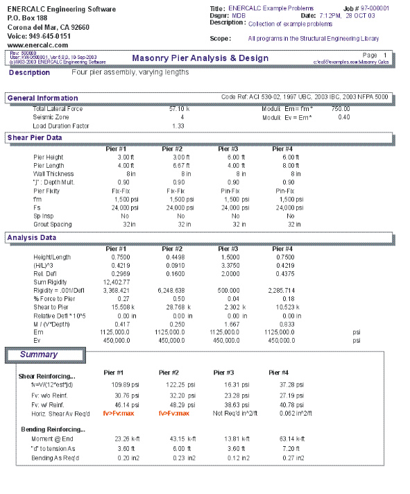
This program provides design and analysis ability for masonry shear wall sections subject to in-plane lateral loads (parallel to their length). You can model a series of shear pier segments that will each carry a percentage of an applied lateral force based upon the relative rigidities of each segment.
A maximum of five shear piers may be specified, each with its own length, height, thickness, and fixity conditions. Also, each of these piers may have individual allowable stresses for conditions where higher strengths are required for specialized designs of highly stressed sections. A load duration factor can be entered for stress adjustments when the nature of loading changes.
The program automatically determines individual pier stiffness's and distributes an overall single applied lateral load to each pier. Unit shear forces, design shear forces, and bending moments in each pier are calculated and used to determine the required shear and end reinforcing.
Basic Usage
| • | First, enter the Total Lateral Load to be applied to the group of shear piers, including the load contributed by the wall. This load will be distributed to each pier in proportion to their relative rigidities. The Load Duration Factor is used to modify the allowable stresses. |
| • | The Design Data section provides all data entries for the group of piers. Pier Height, Length, and Thickness define the pier dimensions to be used for rigidity calculation and stress/reinforcing evaluation. The "j" entry is used to design the wall's stress block depth, used to calculate shear and bending depths. Fixity Code defines the end restraint condition of the wall and effects the rigidity calculations. You can also specify Special Inspection and Grouted Cell Spacing, both of which will effect the allowable stresses for both shear and bending. |
| • | After all data has been entered, calculate the program and review the interaction values in the Summary section. You will notice that all stress components for all load combinations and locations are listed for your review. Continue to modify the Design Data and recalculate until all interaction values are below acceptable levels. |
Unique Features
| • | This program reduces the tedious hand calculation process of determining rigidities, calculating stresses, and then performing the whole operation over again with each refinement. |
| • | In addition to determining forces by relative rigidities, the program determines actual and allowable shear stresses, and provides the required minimum reinforcement area as needed. |
| • | Assumptions & Limitations |
| • | Because of the complexity in determining the rigidity of a wall system, this program idealizes the pier system by assuming that the wall sections providing Fixity are infinitely rigid, and do not deflect in such a manner as to alter the rigidity of adjacent piers. |
| • | All piers are assumed to act in-line. A complex analysis of shear blocks and combined effects of openings & shear blocks is not performed. |
| • | Self-weight of the wall is not automatically included for seismic in plane load, and must be included in the total applied load. |
Example
The data entry for this example is shown in the screen captures that accompany the Data Entry Tabs and Results & Graphics Tabs sections to follow.
Data Entry Tabs
This set of tabs provides entries for all input in this calculation. While you are entering data and switching between these tabs you can view the desired resulting information on the tabs on the right-hand side of the screen (calculated values, sketches, diagrams, etc.). A recalculation is performed after any entry data is changed. After each data entry you can view the results on the right-hand set of tabs.
General Tab
Total Lateral Force
Enter the total lateral force, acting parallel to the piers, which will be distributed to each pier. Distribution is by relative rigidities.
Seismic Zone
Enter the UBC Seismic Zone.
Load Duration Factor
This factor will be applied to the f'm and Fs values to give the allowables to be used in the analysis.
Moduli: Em = f'm * (entry)
In masonry construction the value of Em (Elastic Modulus of the masonry) is calculated as a multiplier applied to f'm. Enter that multiplier here.
Use Grouting at Face Shells Only?
This item tells the program whether to calculate equivalent solid thickness using just the face cells with grout in the bedding or that all block surfaces that mate with the next block above or below have a grout bed.
Shear Pier Data Tab
Pier Height
This value of pier height will be used to calculate the rigidity and bending moment of each pier. This should be measured in a direction perpendicular to the direction of applied lateral loads.
Pier Length
This length should be measured in a direction parallel to the applied lateral loads, and will be used to determine rigidity, unit shear, and d distances for calculating required shear and bending reinforcement.
Pier Thickness
This thickness will be used to modify the pier rigidity by a factor of thickness/12, to adjust deflections by considering wall thickness. It will also be used to determine the actual shear stresses within the wall. Enter nominal thicknesses.
j
Because most masonry shear piers are not long bending members but actually deep beams, we have allowed the user to enter a particular j factor to be used in determining the distance from maximum tension steel to center of gravity of compression stress block. The pier length will be multiplied by j to determine the d (depth) distance from extreme compression fiber to centerline of tension steel.
Fixity Type Code
Enter the fixity condition of each pier to be used in determining individual pier rigidities. Only Pinned-Fixed and Fixed-Fixed restraint conditions are allowed.
f'm
Enter the allowable masonry strength to be used in the analysis. The allowable bending and axial stresses calculated from F'm are outlined in a later section. If the user has chosen not to use special inspection, both allowable axial and bending stresses will be multiplied by ½.
Fs
Enter the allowable tension strength of the reinforcing to be used. This value will be used as entered to determine the interaction equations for the design being performed.
Special Inspection
In this location, enter a 1" to specify if special inspection will be used, therefore allowing full F'm based masonry stresses to be used. Entering a 0" specifies that special Inspection will not be performed, and a multiplier of ½ will be applied to F'm based allowable stresses.
Grouted Cell Spacing
This entry specifies the spacing at which the vertical cells are grouted, and controls the determination of equivalent solid thickness (recalled from an internal table).
Results & Graphics Tabs
This set of tabs provides the calculated values resulting from your input on the "Data Entry Tabs". Because a recalculation is performed with each data entry, the information on these tabs always reflects the accurate and current results, problem sketch, or stress/deflection diagram.
Results / Summary Tab
fv = V / (12 * EST * j * d)
This is the actual shear stress within each pier, considering the tributary applied force, length, j, and equivalent solid thickness.
Fv w/o Reinforcing
This is the code allowable shear stress for piers without reinforcing.
Fv with Reinforcing
This is the code allowable shear stress for piers with reinforcing.
Horiz. As Required
Reinforcing area required to take shear if the shear stress exceeds the Fv w/o Reinforcing value.
Moment
Calculated moment in the pier using the tributary pier force and pier height.
d to Tension As
This is equal to j times the pier length.
Bending As Required
Using the bending moment calculated above, an iteration process using actual j values is executed to determine the required bending reinforcement to be located at a distance of Pier Length - 8 inches.
Results / Analysis Data Tab
Height / Length
As an intermediate step in calculating the rigidity values, the two applicable height / length ratios are calculated.
Relative Deflection
This relative deflection will be used to determine the relative rigidities using standard equations.
Rigidity
The rigidity value of each individual pier is equal to the inverse of the stiffness.
The formulas are:
DEFL (FIXED) = P H3/(12 * Em) + 1.2 P H/(Ev * Area)
DEFL (PINNED) = P H3/(3 * Em) + 1.2 P H/(Ev * Area) Rigidity = 1/Deflection
Sum Rigidities
This equals the summation of the individual rigidities of all of the piers, and is used as the denominator in calculating the distribution coefficients to each individual pier.
% of Force per Pier
Represents the percent rigidity calculated for each pier, and will be multiplied by the Total Lateral Force to give the forces applied to each pier.
Shear per Pier
This value is simply the % Force Taken Per Pier * Lateral Load, and is the force taken by each pier for the analysis.
Relative Pier Deflection
Using the calculated pier stiffness, this is the deflection that the pier will experience due to the percentage load applied to that pier.
M/(V * Depth)
This intermediate calculation is used to determine the correct formulas used to obtain the allowable masonry shear stresses.
Em
Shear modulus; used as a component in the rigidity calculation
Ev
Shear modulus; used as a component in the rigidity calculation
Sketch Tab
This tab provides a sketch of the beam with loads and resulting values shown. Using the [Print Sketch] button will print the sketch in large scale on a single sheet of paper.
Printing Tab
This tab allows you to control which areas of the calculation to print. Checking a box will signal that the information described by the item will be printed. However, if there is no information in for a particular selection it will not be printed. So these checkboxes are best described as "If this particular area of the calculations contains data then print it".
Sample Printout