|
Slender Wall |

|

|

|

|

|
|
|
Slender Wall |
|
|
|
|

|
Slender Wall
|
Slender Wall |
|
|
|
|
|
|
|
Slender Wall |
|
|
|
|
|
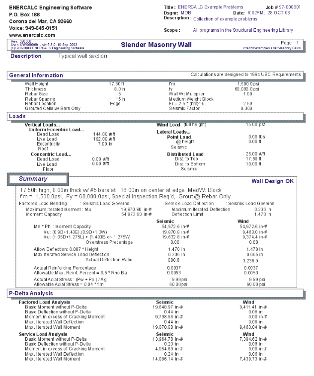
This program provides design and analysis according to the new provisions for design of masonry walls, using the P-Delta deflection considerations now included in the UBC. This method lifts the restriction on H/t ratios, and performs wall analysis using the principles of ultimate strength design. The design method is very similar to that of the Tilt-Up Wall Panel Strip design program contained in the concrete section.
This program uses a 12" wide strip of wall section to represent a typical section of wall. All lateral loads must be adjusted so that the loads acting on the 12" wide section are representative of actual loadings. The program has the ability to apply a lateral wind load, seismic load, partial length uniform lateral load, and a lateral point load to the clear span of the wall section. This variety of loadings should take care of almost every lateral loading case possible.
The P-Delta design of the wall uses a two-stage deflection behavior. For further reference into this design method, please see the UBC or the revised codes from the Masonry Institute of America.
The user may specify masonry and reinforcing strengths, seismic factor, wind load, vertical and lateral loads, vertical load eccentricities, and wall construction. The program determines the wall capacity, actual deflections considering P-Delta effects, and solves for the final moments obtained through iteration of the P-Delta effects. Deflection analysis is provided for both service and factored load cases.
The user reaches a final design by modifying wall thickness, rebar size, and rebar spacing until no overstress condition exists and the deflection limits prescribed in the code are satisfied.
Basic Usage
| • | Entering Stress Data will define the material strengths, grouting status, inspection status, and the values defining lateral seismic and wind loads. The Wall Weight Factor is used as a multiplication factor on the internally stored wall weights (see specific item). |
| • | The Wall Data section is used to enter the clear span, thickness, and reinforcing. These values can be continually modified during the design process to achieve a satisfactory design (satisfying both stress and deflection criteria). |
| • | Vertical Loads can be applied to the wall, both eccentrically and concentrically with the wall centerline. These loads allow you to specify roof loads and additional loads due to equipment platforms or an extended wall segment above the top of the wall. |
| • | Lateral Uniform or Point Loads can be applied to the wall strip, which can be used to simulate lintel-to-jamb loads. These lateral loads can be due to either wind or seismic forces. |
| • | The above entries are all that are required to completely specify a wall section. Calculating the program will perform a factored load analysis for maximum moments and a service load analysis to determine maximum deflections. This analysis is executed simultaneously for both wind and seismic load cases. |
| • | You can then proceed to Check Actual And Allowable Moments, deflection ratios, reinforcing percentages, and axial stress levels. If any are not within limits, you can modify reinforcing or wall thickness to bring the actual values into compliance. |
Unique Features
| • | This program provides the ability to design tall, slender masonry walls according to the latest UBC Section 2411 provisions. |
| • | Both seismic and wind analyses are performed at once. |
| • | You can apply additional lateral loads to the wall to model lintel-to-jamb type conditions. |
Assumptions & Limitations
| • | You should be fully aware of this design procedure for masonry walls. It yields designs that give tall thin walls less reinforcing than earlier working stress methods (where Height/Thickness ratios were limited to 36). |
| • | This program uses ultimate strength principles for the analysis and deflection determination of the wall section. |
| • | Deflection is determined using a two stage load-deflection curve. The deflection of the wall when the moment is LESS than the cracking moment will be based on the gross moment of inertia. To obtain deflections beyond that point, the difference between actual moment and cracking moment is applied using the cracked section moment of inertia. This load-deflection behavior is based on an extensive testing program that led to the adoption of this new design method in the UBC. |
Example
The data entry for this example is shown in the screen captures that accompany the Data Entry Tabs and Results & Graphics Tabs sections to follow.
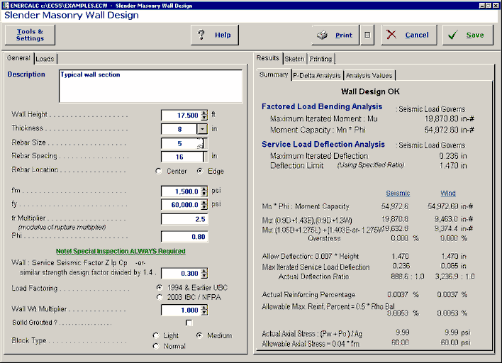
Data Entry Tabs
This set of tabs provides entries for all input in this calculation. While you are entering data and switching between these tabs you can view the desired resulting information on the tabs on the right-hand side of the screen (calculated values, sketches, diagrams, etc.). A recalculation is performed after any entry data is changed. After each data entry you can view the results on the right-hand set of tabs.
General Tab
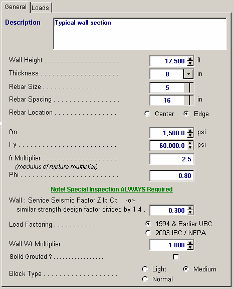
Wall Height
The unsupported wall height is measured from the points of lateral support at the base and roof/second floor. This distance is used to determine moments in the wall due to applied lateral seismic or wind loads.
Thickness
Wall thickness to be used in design analysis. Please enter the NOMINAL thickness; Internal tables will evaluate the actual thickness to be used in the calculations. Thickness can be 6", 8", 10", 12", 14", and 16" inches.
Rebar Size
Enter the rebar size number which should be used. Note that rebar area is not calculated, but recalled from an internal table (#11 and #14 bars are not allowed).
Rebar Spacing
This indicates the 8" Module rebar spacing to be used for design analysis.
Rebar Location
Select Center or Edge. The actual rebar depth will automatically be retrieved from an internal table.
f'm
This is the allowable masonry strength used in the analysis. The allowable bending and axial stresses calculated from f'm are outlined in a later section.
Fy
Enter the allowable tension strength of the reinforcing to be used. This value will be used as entered to determine the interaction equations for the design being performed.
fr Multiplier
Enter the multiplier to be applied to f'm to calculate the modulus of rupture.
Phi
The value for Phi (capacity reduction factor) is dependent upon special inspection. 0.80 is used for inspected construction, 0.50 for uninspected. This capacity reduction factor is applied to the calculated moment capacity to take into account such factors as quality control, use, and design/analysis assumptions.
Wall Seismic Factor
The seismic factor will be applied to the actual wall weight to generate the lateral load for seismic analysis.
Load Factoring per Code
Select the core that will govern the internal factoring of entered loads for calculation of ultimate (factored) loads applied to the wall.
Wall Weight Multiplier
This factor is available for you to modify the wall weight recalled from the internal tables. The value will be applied directly to the internal wall weight and the product displayed as Wall Weight.
Solid Grouted?
Enter YES if the wall will be solid grouted (regardless of steel spacing). Entering NO specifies that cells containing vertical reinforcing will be grouted. This input effects the calculation for wall weight and equivalent solid thickness
Block Type
This entry controls what block type is being used for determining the wall weight to be recalled from the internal tables. Select Lightweight, Medium Weight, or Normal Weight.
Loads Tab
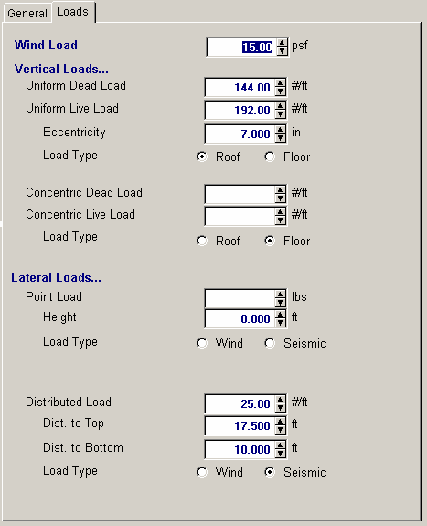
Wind Load
Enter the wind load (in psf) that should be applied laterally to the full height of the wall. This load will be combined with any added lateral loads that are specified as Wind.
Vertical Loads
Uniform Loads
These uniform loads are applied to the wall at the specified eccentricity. The program resolves this loading to an axial load and concentrated moment applied at the top of the Unsupported Height. The concentrated moment is always ADDED to the moments created from wind and seismic forces, and decreases to zero at the lower lateral support. This load is included in both bending and axial load computations.
Uniform Load Eccentricity
The user may specify that the uniform dead and live load is applied at an eccentricity. When determining maximum moments, the moment created by this eccentric load is always ADDED to the lateral load moments, regardless of whether eccentricity is positive or negative.
Concentric
You can specify an axial load applied to the top of the wall, such as load carried down from a floor above or just an added load. This load is considered axial stress only. (No P-Delta moments calculated).
Lateral Loads
Point Lateral Load
This load is applied to the 12" wide strip of wall in addition to the lateral load due to wind and seismic forces. If it is a seismic load, the value should be entered after applying the code specified seismic factor . This additional lateral load is intended to enable the user to model a section of wall or Jamb Strip when additional loads are applied to it (e.g. from a lintel contributing lateral wind/seismic load to a jamb strip through a horizontal bond beam at the opening head).
Height From Base
Enter the distance from the bottom of the wall to point of application of the concentrated point load.
Point Type: Wind/Seismic
This specifies whether this added point load is due to seismic or wind forces.
Uniform Lateral Load
This load is applied to the 12" wide strip of wall in addition to the lateral load due to wind or seismic forces. For seismic loads, it should be entered after applying the code required seismic factor . This additional lateral load enables the user to model a section of wall or jamb strip when additional loads are applied to it, (i.e. due to a lintel spanning horizontally, constructed integrally with the wall).
X-distance To Bottom
Enter the distance from the bottom of the wall to the start of the uniform lateral load.
X-Distance To Top
Enter the distance from the bottom of the wall to the end of the uniform lateral load. This height will be automatically limited to Unsupported Height if it has been specified as greater.
Uniform Type: Wind/Seismic
This specifies whether this added uniform lateral load is due to seismic or wind forces.
Results & Graphics Tabs
This set of tabs provides the calculated values resulting from your input on the "Data Entry Tabs". Because a recalculation is performed with each data entry, the information on these tabs always reflects the accurate and current results, problem sketch, or stress/deflection diagram.
Results / Summary Tab
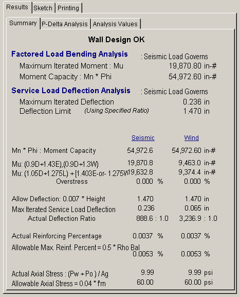
M-n * Phi
From the analysis presented in the section titled Analysis Values, the maximum moment capacity of the wall for both seismic and wind loading is displayed.
M-u
From the analysis to follow, the maximum factored load moment acting on the wall from both seismic and wind loads is displayed.
Maximum Overstress
If the wall section you have specified exceeds the actual moment, the percentage of overstress is listed.
Maximum Allowable Deflection
The maximum allowable deflection per code is .007 * Clear Wall Height (distance between lateral supports). Your design should always be checked so that this requirement is satisfied, since the deflection limitation design philosophy is the primary factor allowing slender masonry walls.
Max. Iterated Service Deflection
This is the calculated deflection at the mid-height of the wall using service loads. The program calculates this deflection by iterating P-Delta moments and the resulting increase in deflections caused by these moments.
Actual Ht /Service Deflection
For both seismic and wind loading cases, the clear wall height is divided by the Service Load Deflection @ Convergence.
Actual Reinf. %
This is the actual reinforcing percentage ratio for the rebar and wall thickness specified.
Allowable %
This is the maximum allowable steel percentage by UBC code and varies with grade of steel.
Actual Axial Load
This is the actual axial stress on the 12" wide strip, caused by the applied vertical loads and wall weight ABOVE mid-height. When the wall is partially grouted, the equivalent solid thickness is used to calculated the area instead of the actual wall thickness.
Allowable Axial Load
The allowable axial load that can be imposed on the 12" wall section subjected to bending is .04 * f'm * AGROSS. This allowable axial load is listed here for comparison with the actual value listed below. The designer should always verify that this allowable load is greater than the actual load.
Results / P-Delta Analysis Tab
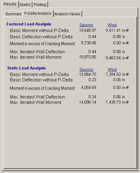
Factored and Service Load Stress Analysis
These two sections provide the details of the iterative analysis of the wall section using factored and service loads. The factored load analysis is used to determine maximum moments in the wall, accrued by iterative recalculation of deflections and their effect on P-Delta moments.
The service load analysis uses unfactored loads to iterate wall deflections and moments. The Height/Service Deflection ratio will be checked against the allowable limit.
Both methods follow the same procedure; calculate moment, calculate deflection, and then recalculate wall moments. UBC formula 11-7 is used to calculate moments and deflections:
MU = WU*H2/8 + POU*e/2 + (PWU+POU)*DU
DS-MAX <= 0.007 * Wall Height
DS =5*MCRACKED*h2/(48*EM*IG) + 5*(MS-MCR)*h2/(48*EM*ICR))
The second term of the deflection equation is ignored when negative.
Basic Moment w/o P-delta
This is the mid-height moment induced from lateral seismic and wind loads and roof loads applied at an eccentricity before addition of P-Delta effects.
Basic Deflection w/o P-delta
Basic deflection is calculated using the basic moments applied to the equation presented above. For moments up to the cracking moment, the gross moment of inertia is used to find deflection. For any portion of the moment that exceeds the cracking moment, the cracked section moment of inertia is used to determine additional deflections.
Basic Deflection w/o Excess Moment
If the basic moment is greater than the cracking moment (SGROSS*FR), the excess portion must be identified so a proper deflection analysis can be performed.
Maximum Iterated Deflection
After the repeated iteration of moment and deflection, the final value of deflection (that causes negligible additional deflection) is listed here.
Maximum Iterated Moment
The total moment at deflection convergence is calculated by iteration. Starting with the basic load deflection, the P-Delta moment is found and a subsequent deflection calculated (using the same "compound" moment of inertia method).
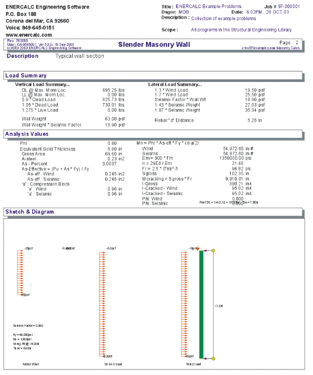
Results / Analysis Values Tab
The following values are used for the design and analysis of slender masonry walls. All of these values apply for both wind and seismic analysis with the exception of Moment of Inertia:Effective, which is different due to different AsEFF values being based on different factored axial loads.
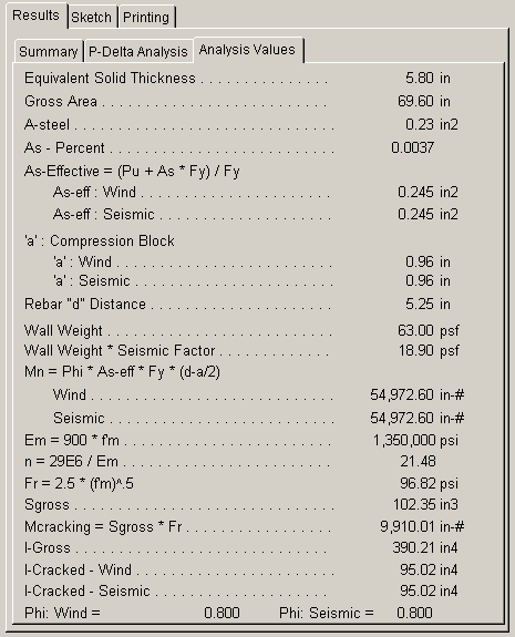
Equivalent Thickness
The equivalent solid thickness depends upon NOMINAL the wall thickness and rebar spacing, and is obtained from a table stored within the program. When the wall has been specified as solid grouted (see item previous), this thickness is equal to the actual, not nominal, wall thickness. Please see table on page M-8
Gross Area
Gross area of the 12" wide strip equals Equivalent Solid Thickness * 12".
As
Reinforcing steel area in a 12" length of wall.
Asteel/Agross
This value is: As/Awall-EFFECTIVE
As-eff.
This is the steel reinforcing area in a 12" length of wall modified for the effect of axial load using the UBC equation specified in section 2312:
AS-EFF = (AS*fY + PU)/fY
"a"
This is the typical ACI equation for determining the depth of the equivalent compressive stress block used for analysis.
Mn
This is the calculated maximum moment capacity of the section whose values for allowable stresses, reinforcing size and spacing, and effective area of steel are given.
Em
The modulus of elasticity for masonry is calculated as:
EM = 750 * f'm
Fr
The modulus of rupture is calculated by multiplying the value you've entered by f'm1/2
S-gross
Gross section modulus for 12" of wall width :
12" * (Actual Wall Thickness)2 / 6
S * Fr
This is the Cracking Moment, the maximum moment the wall can take as a solid section without any reinforcing.
Igross & Icracked
Gross and cracked section moduli of the wall to be used in the deflection analysis.
Wall Weight
The wall weight is automatically recalled from an internal table of weights, considering rebar spacing, wall thickness, and status of solid grouting. The table is based on light, medium, and normal weight block.
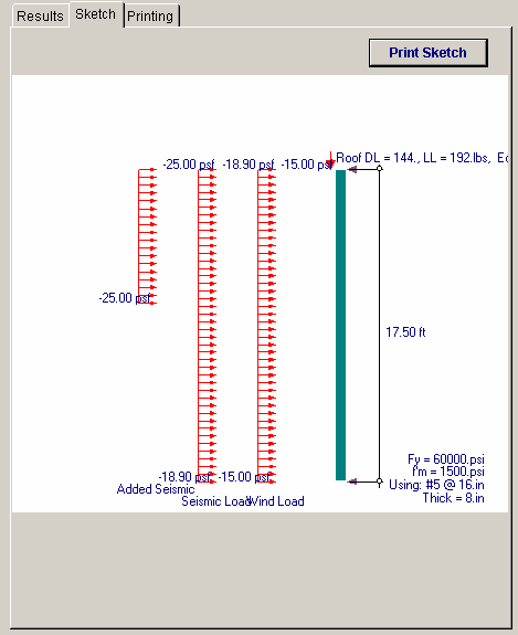
Sketch Tab
This tab provides a sketch of the beam with loads and resulting values shown. Using the [Print Sketch] button will print the sketch in large scale on a single sheet of paper.
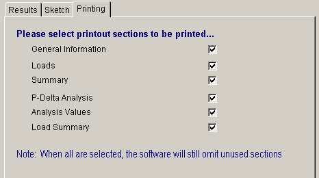
Printing Tab
This tab allows you to control which areas of the calculation to print. Checking a box will signal that the information described by the item will be printed. However, if there is no information in for a particular selection it will not be printed. So these checkboxes are best described as "If this particular area of the calculations contains data then print it".
Sample Printout