|
Steel Beam w/Torsion |

|

|

|

|

|
|
|
Steel Beam w/Torsion |
|
|
|
|

|
Steel Beam w/Torsion
|
Steel Beam w/Torsion |
|
|
|
|
|
|
|
Steel Beam w/Torsion |
|
|
|
|
|
This program analyzes rolled AISC steel W, H, S, M, C, B, JR, and MC I sections and channels subjected to applied loads causing torsion within the beam. Both plane and bending stresses are determined in addition to typical AISC code checks for compactness and lateral-torsional buckling.
Two end fixity combinations are allowed to separately determine torsional and bending stresses; Pinned/Pinned and Fixed/Fixed. With these end fixity conditions combined with torsional analysis, a variety of load and span conditions can be analyzed.
In order to perform the extensive torsional analysis, the typical torsional equations presented in the AISC publication (Torsional Analysis of Members ©1983 ), have been derived and used to calculate analysis values at ½50 span increments. Only cases # 3, 4, 6, 7, and 12 have been incorporated:
| • | Case 3: Ends torsionally pinned with a concentrated twisting moment applied between supports. |
| • | Case 4: Ends torsionally pinned with a uniform load applied to the beam at an off-center eccentricity. |
| • | Case 6: Ends torsionally fixed with a concentrated twisting moment applied between supports. |
| • | Case 7: Ends torsionally fixed with a uniform load applied to the beam at an off-center eccentricity. |
| • | Case 12: Left end torsionally fixed, right end torsionally pinned, uniform load applied to the beam at an off-center eccentricity. |
These stresses are combined with the actual stresses from normal X-X axis bending and compared with allowable values based on compactness and lateral buckling criteria.
Final stresses are determined by combining major axis bending and shears with torsional moments. Normal and shear stresses from plane bending are combined with torsional bending, warping shear, and pure torsional shear forces to give a final analysis of the actual stresses, deflections, and rotations of the beam's slenderness effects.
Basic Usage
| • | Enter the span length of the member. (Please note that cantilevers are not allowed.) Torsional Fixity indicates whether the flanges are capable of Warping . Warping is a condition where the two flanges can move so that they are no longer parallel. Bending Fixity indicates if the ends are free to rotate about the beam's X-X axis. When Pin/Pin is chosen for either end, no end normal bending or warping torsional moments will occur. |
| • | If your beam is subjected to loads of a short term nature, Load Duration Factor can be used to increase the allowable stresses. You can also specify to include the weight of the beam as a uniform dead load automatically from the member you've chosen. When the beam's compression flange is unbraced for lateral buckling, enter the distance you wish to use for allowable stress calculations. |
| • | Applied Loads. We've provided the capability to enter up to 14 loads on the member, all of which create torsional or normal bending stresses. All loads also have dead, live, and short term components. Uniform and point loads can be applied at eccentricities causing torsion. Bending moments create purely normal axis bending, and twisting moments apply a concentrated torque to the beam. (i.e. opposing point loads at equal lateral eccentricity). |
| • | Section Properties can be entered by using the built-in section property databases. Please see the following two sections on using this capability. |
Unique Features
| • | Combine applied bending loads with torsional loads for a complete stress analysis of the entire beam. |
| • | Specify different end fixities for bending and torsional analysis procedures. |
| • | Handles up to 14 different loads which can be dead, live, or short term. |
Assumptions & Limitations
Only wide flange and channel type sections are allowed....tubes, pipes, tees, and angles are not supported.
Steel Section Database
Built into the software is a complete database of common rolled sections available from various mills in the United States. On each tab labeled #1, #2, etc. there will be a button that looks like this:
![]()
This button displays the steel section database as shown below.
On this window there are various controls and options.....
Steel Database : Allows you to select between several common shapes databases.
Section Type to Display: Allows you to select which steel section designation to display in the list. These shapes conform to the American Institute of Steel Construction shape designations. To make your selection simply move the mouse over the letter(s) and when the highlight activates left-click once with your left mouse button.
Depth Range: This item allows you to specify depth limits to be used for selecting which sections to display in the list. When the checkbox to the left is not checked the selection wording and entries will not appear and all sections will be displayed. These dimensions are compared to the "Depth" dimension of the sections.
Class Range : This item allows you to specify the limits in "Depth Class" to be displayed in the table. The "Depth Class" of a section is the first numeric number in the sections name. For instance a wide flange W14x22 is in depth class "14". a channel C9x15 is in depth class "9", and a L5x3x1/4 is in depth class "5".
Equal & Unequal Legs : These two buttons appear when you have selected section type "L" which are single angles. The limit the display of the list to angle with equal dimension or unequal dimension sides.
Equal Legs, Long Leg Vertical, Short Leg Vertical: These three buttons appear when you have chosen to display section type "LL". These control the display of sections between pairs of angles with both sides of equal length, of unequal side length angles paired with the LONG side together, and unequal side length angles paired with the SHORTside together.
Square & Rectangular Tubes: These two buttons appear when you have chosen section types TS or HSS-T. These are square tubular sections. You can choose to display only square tubes or alternately tubes with unequal sides.
Sort Tabs for Database Table : Immediate above the database list of sections you will see tabs looking like this....
When selected each tab will sort the list in the order described by the text on that tab.
Sort order : These two buttons allow you to chose the list order of the sections. The sorting order will be according to the sort tab selected and shall be in ascending or descending order.
Database Table Itself : The main area on the window will be where the steel sections are displayed as a result of all of your choices as described above.
[Select] : This button is displayed when you have clicked on the [Section] button when you press [Select] the section in the list that is currently highlighted will be selected and the name and data brought into your calculation.
[Insert]: Use this button to add a steel section to the database. When pressed you will see the following window:
The only really important item to enter is the "Type" item. This specifies what standard rolled section type your section is. This item is used internally by the program to decide which stress analysis method to use for determining the sections allowable stress, how to consider unstiffenned elements, and many other code checking items.
[Change]: Will display the same window as above but allow you to change section properties.
[Delete] : Will enable you to delete sections. Note: No sections in the supplied database can be deleted. Only Sections that you ad can be later deleted.
[Cancel]: Exit the steel database window.
ASD & LRFD Design Modes
Allowable Stress Design and Load & Resistance Factor Design as specified by the American Institute of Steel Construction is provided by this program. Only screen captures and descriptions for ASD are presented in this book. More detailed LRFD documentation will be added and will be available in the electronically delivered versions of this book. Check these locations for electronic media:
| • | Latest Adobe Acrobat PDF documentation file here: ftp://208.36.30.226/sel5.pdf. |
| • | Latest Windows Help system file here : ftp://208.36.30.226/enercalc.hlp. |
| • | Internet HTML help documentation presented as web pages at www.enercalc.com/sel_help. |
Example
The data entry for this example is shown in the screen captures that accompany the Data Entry Tabs and Results & Graphics Tabs sections to follow.
Data Entry Tabs
This set of tabs provides entries for all input in this calculation. While you are entering data and switching between these tabs you can view the desired resulting information on the tabs on the right-hand side of the screen (calculated values, sketches, diagrams, etc.). A recalculation is performed after any entry data is changed. After each data entry you can view the results on the right-hand set of tabs.
General Tab
This tab provides data entry for everything except loading on the beam.
Beam Span
Enter the span length here. No cantilevers are allowed.
Unbraced Length
This is the user specified unbraced length of the compression flange, used to determine the allowable F'b based on flange buckling criteria.
Torsional End Fixity
Enter the end fixities to use in determining the restraint case to be selected. The end fixities should be thoroughly understood, since warping restraint is difficult to achieve in actual practice.
Bending End Fixity
Enter the end fixity combination that will be used to calculate bending moments due to applied loads (not torsional forces). Only Fix/Fix and Pin/Pin conditions are allowed.
Steel Section
This is where you specify the rolled steel section to be used in the design. There are two ways to enter & specify the section.
| • | Use the [Section] button to retrieve the section from the built-in steel database. See the description given previously for more information. |
| • | Type in the section name and the program will automatically look through the database for a match. Upper or lower case is fine. If found the name and numeric section properties will be retrieved into this calculation. The numeric properties will be seen on the "Section Properties" tab. |
Fy
Yield stress of the steel used for the member being analyzed. All allowable stresses are calculated in accordance with the latest AISC Specifications.
Load Duration Factor
This factor applied to the calculated allowable stresses and displayed as Allowable Stress in the Summary section.
Elastic Modulus
Although rarely does this need to be changed, enter the elastic modulus of the steel material.
Uniform Loads Tab
Up to seven full or partial length uniform loads with dead, live, and short term components may be applied anywhere on the span. The "Start" and "End" values refers to the distance from the left support to where the beginning of the distributed load is applied. To specify loads on the left cantilever use negative distances.
Point Loads Tab
You may apply up to eight point loads with dead, live, and short-term components. The Dist. value refers to the distance from the left support to where the point load is applied. To specify loads on the left cantilever, Dist. should be negative.
Moments Tab
Up to eight moments with dead, live, and short-term components may be applied anywhere on the span. Moments with a positive sign impart a counterclockwise torque to the beam (following the right hand rule). The "Location" values refers to the distance from the left support to where the moment is applied. To specify loads on the left cantilever this value should be negative.
Section Properties Tab
This secondary tab is where the steel section properties are listed. The properties shown here are used for the calculation.
The typical steel section measurements are given for the section chosen. When certain sections are used, the measurements will not conform to the typical W section naming conventions used here:
| • | For Tubes , Flange Thickness and Wall Thickness will both be set equal to the tube's wall thickness. rT is not used. |
| • | For Pipe , Flange Thickness and Wall Thickness both equal the pipe's wall thickness. Flange Width and Depth will both be set to the pipe's outside diameter. rT is not used. |
| • | For Channels , rT equals the distance from the flat face to the center of gravity of the section. |
| • | For Tees , rT equals the distance from the top of the flange to the center of gravity of the section. |
| • | For Double Angles, rT equals the spacing between the backs of the angles. |
| • | For Single Angles, rT is not used. |
Results & Graphics Tabs
This set of tabs provides the calculated values resulting from your input on the "Data Entry Tabs". Because a recalculation is performed with each data entry, the information on these tabs always reflects the accurate and current results, problem sketch, or stress/deflection diagram.
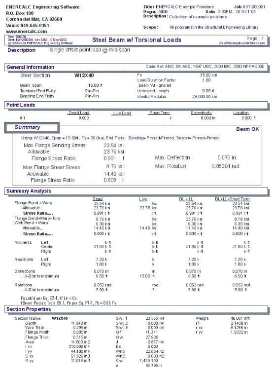
Results / Summary Tab
Maximum Flange Bending Stress
This is the maximum flange bending stress (See Results/Details tab).
Maximum Flange Shear Stress
This is the maximum flange or web shear stress (See Results/Details tab).
Maximum Deflection
Center span deflection is the maximum magnitude (positive or negative) between the supports.
Maximum Rotation
Using the applied loads and their torsional eccentricities, the maximum rotation and its location from the left support is given.
Results / Details Tab
This section provides analysis results for various combinations of dead, live, and short term loads. Each column gives values for the combination listed at the top.
Bending
This item gives stresses in the flange due to combined bending and torsional loads. The forces act parallel to the span of the beam, and are fb stresses to be compared with the allowable bending stress F'b. To determine the maximum value presented here, a stress diagram is internally constructed at 250 points along the beam and is then evaluated for maximum values.
Bending + Warping Bending stress is calculated by dividing the actual moment by section modulus. Warping torsional stress is calculated by Es * Wno * j'' is calculated using the typical torsional equations found in the AISC reference, and varies along the span with torsional moment.
The allowable bending stress is evaluated considering beam slenderness.
Shear
This item gives shearing stresses in the flange and web due to the combined action of bending and torsional stresses.
Flange The flange shearing stresses have three components: bending, warping, and Torsional. Bending flange shear stresses are calculated using (V*Qf)/(Ixx* Tf).
Warping shear stress is calculates using (Es*Sw*j''')/Tf. Torsional flange shear stress is calculated using (G*Tf*j').
Web The web shearing stresses have two components: bending and torsion. Bending web shear stresses are calculated using (V*Qw)/(Ixx* Tw). Torsional web shear stress is calculated using (G*Tw*j').
The allowable shear stress = 0.4 Fy.
Moments
M+ and M- are determined by checking 250 points along the span for maximum and minimum values.
Reactions
These are simply the left and right beam reactions due to the load combinations used.
Deflections
Center span deflection is the maximum magnitude (positive or negative) between the supports.
Rotations
Using the applied loads and their torsional eccentricities, the maximum rotation and its location from the left support is given.
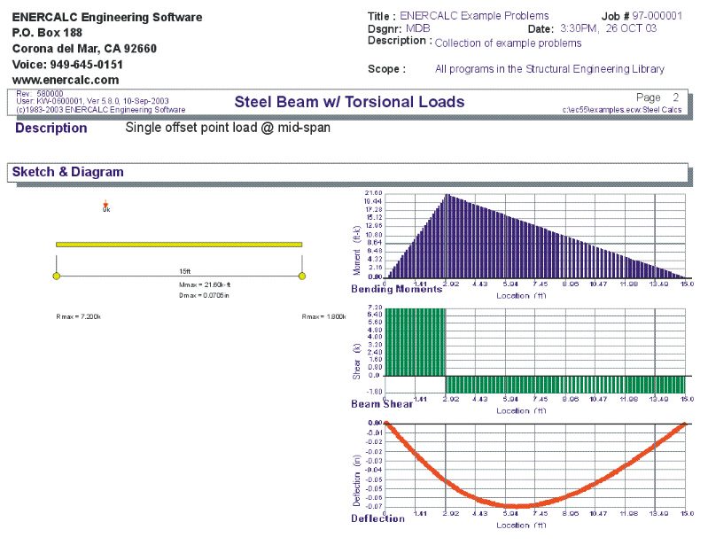
Sketch Tab
This tab provides a sketch of the beam with loads and resulting values shown. Using the [Print Sketch] button will print the sketch in large scale on a single sheet of paper.
Diagrams Tab
This displays a moment, shear, and deflection diagram for the beam with the applied loads and end conditions. Note the two tabs...."Graphic Diagram" and "Data Table". The Data Table tab provides the entire internal analysis at the 1/500th points within the beam.
Printing Tab
This tab allows you to control which areas of the calculation to print. Checking a box will signal that the information described by the item will be printed. However, if there is no information in for a particular selection it will not be printed. So these checkboxes are best described as "If this particular area of the calculations contains data then print it".
Sample Printout