Wood Shear Wall |
  
|
Wood Shear Wall |
|
Basis
The NDS Special Design Provisions for Wind & Seismic allows for three approaches to wood shear wall design:
1. Force Transfer Shear Walls
2. Perforated Shear Walls
3. Individual Full-Height Wall Segment Shear Walls.
Force Transfer Shear Walls and Perforated Shear Walls allow the designer to use more favorable analysis assumptions, and offers some benefits in terms of construction details. But it comes at a cost of the designer having to perform more calculations and designs to follow the load path through all of the headers, jambs, sills, etc., and their connections.
At present, the Wood Shear Wall module implements the Individual Full-Height Wall Segment Shear Walls method. This is the most straightforward method from the design standpoint. This method still requires the evaluation of h/b ratios to decide whether to eliminate slender segments or suffer the imposed reduction on the nominal shear capacity based on the slenderness of each panel in the wall. This method does not require consideration of the reduction factor (Co) that applies to Perforated Shear Walls.
Section 4.3.2.1 of SDPWS 2021 refers to Section 4.3.3, for the reduction due to aspect ratio. But the implementation within ENERCALC SEL goes a little further by allowing the user to specify openings. The module then takes the defined openings and considers only the solid stacked portions of remaining wall as being effective at resisting lateral loads. So the module actually applies the 2b/h reduction as permitted in Exception 1 in Section 4.3.5.5.1, rather than using the aspect ratio formula in Section 4.3.3. It is always more conservative than the adjustment in 4.3.3, but it allows the module to handle shear walls in a line because, by definition within the module, all segments will be “sheathed with the same materials and construction”.
Overview
The Wood Shear Wall module allows the user to define overall geometry, openings (if any), sheathing type, chord member species, grade, and size, applied loads, and a footing (if desired). The module then evaluates the resulting shear panels, chords, and footing (if defined).
Sheathing is evaluated for aspect ratio and unit shear due to load combinations that include either wind or seismic. The module considers the selected sheathing type, sheathing thickness, fastener size, blocking condition, and the species of the supporting framing. It then automatically incorporates any necessary adjustments to the nominal unit shear values from the Special Design Provisions for Wind and Seismic on the basis of sheathing type, aspect ratio, and the species of the supporting framing. The result is a required fastener spacing for each panel in the wall.
Chords are evaluated for tension and compression due to load combinations that include either wind or seismic. The moment in a given shear panel is assumed to be coupled out at the location of the chords, resulting in tension and compression forces. Any applied vertical loads that may be present are combined with the wind or seismic chord forces, and the resulting loads on the chords are evaluated as per the requirements of the NDS.
Footings (if defined) are evaluated for soil bearing pressure, overturning, and one-way shear and flexure of the cantilevered end projection.
There are certain items that are not explicitly evaluated by this module, and the user should be aware of the following exclusions: bending or shear in the top plate, bearing on the top plate, out of plane design of the wall sheathing or framing, gravity-only loading on the common studs or chords, bearing on the bottom plate, design of anchorage hardware or connections.
Workflow Process
The general workflow proceeds as follows:
1.The overall height and length of the shear wall are defined on the General tab, along with selections such as the Seismic Design Category, the Design Method, and the Framing and Chord Species and Grade.
2.The sheathing type, thickness, fastener size and blocking conditions is selected on the Sheathing tab. This tab also allows for the specification of sheathing on the second side of the framing when necessary.
3.The chord size is specified on a level-by-level basis on the Chords tab. This tab also allows for the specification of the bracing assumption to be applied in the compression design of the chords.
4.If openings are present in the wall, they can be defined on the Openings tab.
5.Loads of many types can be defined and applied on the Loads tab.
6.If a continuous footing design is desired, the footing geometry and material properties can be entered on the Footing tab.
7.The Load Combinations tab allows for the definition of the load combinations that will be used for the design.
8.The results for the shear panels, chords, and footing (if designed) can be reviewed in the Results panel in the lower portion of the screen.
General
Description: Enter a free-form description of the current wall design for reference.
Total Wall Length: Enter the overall length of the shear wall in units of feet.
Stud Spacing: Enter the typical stud spacing in inches.
Story Heights: Enter the heights of up to five stories in units of feet. Whenever a value is entered, the input field for the next story height is displayed in case it is needed. The total accumulated height is automatically reported.
Seismic Design Category: Enter the appropriate Seismic Design Category for the wall being designed. This is used to check the selected sheathing type to be sure it is permissible for use in that SDS according to the Special Design Provisions for Wind and Seismic.
Design Method: Select ASD or LRFD to dictate which method will be applied when designing shear panels and chords. Footing design (when requested) is always by LRFD methods.
Framing & Chord Material: Use the icon to access the Wood Reference Design Values database in order to select the species and grade of wood used for the chords and common framing in the wall.
Sheathing
Select SDPWS Construction Table: Choose the table from which the sheathing will be selected.
Select Main Sheathing: Select a tabular entry to represent the sheathing type, sheathing thickness, fastener size/penetration, and in some cases the blocking condition.
Nominal Shear Capacities: The program displays the nominal shear capacities for seismic design and for wind design directly from the selected table. These are nominal values which still need to be modified for use in design, such as with a phi factor or factor of safety and with any applicable adjustments such as for aspect ratio or specific gravity of the supporting framing.
Table 4.3A Footnote 2 is applicable: (Only visible for some sheathing selections) Use this checkbox to indicate if a specific condition exists as described in detail in the referenced footnote in Table 4.3A of the Special Design Provisions for Wind and Seismic.
Sheathing is Blocked: (Only visible for some sheathing selections) Use this checkbox to indicate if the sheathing is blocked or not. This setting has an effect on some of the allowable aspect ratios.
Sheathing on 2nd Side: Use this checkbox to indicate that there is sheathing of some sort on the other side of the framing.
Use Same as Main Sheathing: A convenience option that automatically sets the Sheathing on 2nd Side to be identical to the sheathing on the Main side.
Note: If sheathing is specified on the second side, and if the sheathing comes from the same Construction Table as the Main Sheathing, then the blocking setting for the 2nd side will automatically be assumed to be the same as the blocking setting for the Main side.
Chords
The Chords tab will automatically display one row of chord definition data for each story that was defined on the General tab.
Chord Member Size: Use the drop-down list box to select the size of the sawn lumber member(s) that will be used at the chord locations for the given level. Note that the program will automatically determine the number of chord members required at each location. So for example, if the wall was generally going to be constructed of 2x4 framing, then this input should be set to "2x4". Once the analysis and design has been completed, the program will report how many 2x4s should be ganged together to safely resist the imposed chord forces at each location.
CF: Size Factor: Enter the appropriate Size Factor for the chord member size, species, and grade being entered.
Area per Chord: The program reports that cross sectional area of one member of the selected size for reference.
Maximum Chord Stress Ratio: Enter the maximum permissible chord stress ratio. Typically 1.0 using current design methods and load combinations.
Wood Chord Strength Calculation: This setting offers two options for defining the bracing of chord members when the allowable compression stress is calculated:
•The option named "Treat all chords as fully braced about both axes" implies that all chords are braced against column buckling. The physical model for this option might be a situation where chord members always occur at "L" or "T" shaped intersections, such that the sheathing prevents buckling in the plane of the shear wall, and the intersecting wall prevents buckling out of the plane of the shear wall. (These conditions are probably not common.)
•The option named "Assume all chords unbraced out of plane of wall for story height" implies that the sheathing prevents buckling in the plane of the shear wall, but nothing prohibits column buckling of the chord member out of the plane of the wall. This is the condition for the chords at the end of an isolated straight panel of wall where no perpendicular walls intersect the shear wall at the chord locations.
Openings
The Openings tab allows openings to be defined in the shear wall.
Add: The Add button opens the Add Opening dialog. The dialog automatically numbers the openings that are added, and it collects the geometric information necessary to locate and size the opening. The Add Opening dialog also checks the alignment of defined openings to ensure that all jambs are aligned.
Edit: By selecting an existing opening in the list, the Edit button allows the selected opening to be revised.
Delete: By selecting an existing opening in the list, the Delete button allows the selected opening to be removed.
Renumber: The Renumber button allows existing openings to be renumbered in a logical order by working from left to right and then from bottom to top.
The graphic display offers checkboxes to independently display or hide:
•Openings
•Shear Panel callouts
•Chord graphics and callouts
•Panel and opening dimensions
•All loads
Note: This module is predicated on the design assumptions of the Individual Full-Height Wall Segment Shear Walls method. This method disregards the shear resistance of portions of shear walls above and below openings. This leads to two important considerations regarding the use of openings:
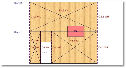
1.In multi-story models, any opening in one story must not partially overlap an opening in a different story. If they overlap at all, they must match exactly. Envision vertical lines at the jambs of an opening, and project them to the top and bottom of the entire wall. Those jamb reference lines must not cross any other opening. If anything, they can only align with other jambs. The Add Opening dialog will warn if this condition is being violated by having partially-overlapping openings in any story. This may require enlarging some openings so that they respect the jamb locations of adjacent openings, or it may require applying the module only to the solid portions of the wall that remain after the openings have been omitted.
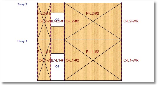
2.The presence of an opening within a given story, creates a zone that is ineffective at resisting shear. The ineffective zone is defined by the width of the opening and it extends for the full height of that story. This means that it is not necessary to model stacked openings within a given story. In fact, doings so will cause an error.
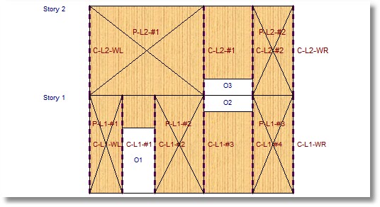
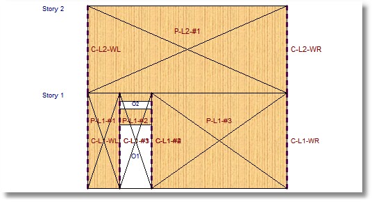
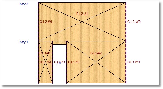
See the following diagrams for some acceptable and unacceptable opening geometries:
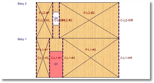
NG - Jambs of openings do NOT align
Here is how to fix it:
OK - Jambs of openings align properly
NG - Opening crosses top of story
Here is how to fix it:
OK - Large opening modeled as 2 separate openings
NG - Stacked openings within a story
Here is how to fix it:
OK - One opening accomplishes the task
Note: When using the self-weight functions for Dead Load and for seismic load, the program does not deduct any weight for openings. In other words, the program assumes that the unit weight of the window, door, louver, etc. in the opening, is approximately the same as the unit weight of the wood-framed construction it is replacing.
Loads tab
The Loads tab provides several sub-tabs for the convenient definition of many different types of loads that could potentially act on a shear wall system.
General
The Wall Self Weight category offers inputs for the following:
Consider Wall Weight: This category provides options to automatically consider the wall self-weight:
•As vertical Dead load - a way to request that the program use the unit weight described above to calculate a dead load
•As Seismic load - a way to request that the program use the unit weight described above to calculate a lateral seismic load using the value of Cs described below
Weight: (Only displayed when one of the options above has been selected.) Enter the unit weight of shear wall construction in psf.
Cs: Seismic Response Coefficient: (Only displayed when the "As Seismic load" option above has been selected.) Collects the value of Cs by which the unit weight would be multiplied to determine the seismic load due to the self-weight of the wall if that option is selected.
Soil over Footing: category is only displayed if the "Specify a Footing" option is selected on the Footing tab. This category offers inputs for the following:
Soil depth over footing: Enter the depth of soil above the top of the footing in units of inches. This value is used to determine loading on concrete footings when one is designed. This value will affect the reinforced concrete design, the soil bearing pressure, and the overturning ratio.
Soil density: Enter the density of soil above the top of the footing in units of pcf. This value is used to determine loading on concrete footings when one is designed. This value will affect the reinforced concrete design, the soil bearing pressure, and the overturning ratio. If no footing design is requested, this value has no influence on the remaining calculations.
Added Overburden Load over Footing: category is only displayed if the "Specify a Footing" option is selected on the Footing tab. This category allows the user to specify superimposed load on the top of the footing for all of the common load cases. This value will affect the reinforced concrete design, the soil bearing pressure, and the overturning ratio.
Vertical Point
Add: The Add button opens the Add Point Load dialog. The dialog allows vertical point loads of all load cases to be defined and located with respect to the lower left corner of the wall. Note: Positive magnitudes are assumed to act downward.
Edit: By selecting an existing load in the list, the Edit button allows the selected load to be revised.
Delete: By selecting an existing load in the list, the Delete button allows the load opening to be removed.
Vertical Uniform
Add: The Add button opens the Add Uniform Load dialog. The dialog allows vertical uniform loads of all load cases to be defined and located with respect to the lower left corner of the wall. Note: Uniform loads can be specified as partial-length loads by specifying the start and end locations of the load with respect to the left edge of the wall. Positive magnitudes are assumed to act downward.
Edit: By selecting an existing load in the list, the Edit button allows the selected load to be revised.
Delete: By selecting an existing load in the list, the Delete button allows the load opening to be removed.
Lateral Point
Add: The Add button opens the Add Point Load dialog. The dialog allows lateral point loads of all load cases to be defined and located with respect to the lower edge of the wall. Note: Positive magnitudes are assumed to act to the right.
Edit: By selecting an existing load in the list, the Edit button allows the selected load to be revised.
Delete: By selecting an existing load in the list, the Delete button allows the load opening to be removed.
Lateral Uniform
Add: The Add button opens the Add Uniform Load dialog. The dialog allows lateral uniform loads of all load cases to be defined and located with respect to the lower edge of the wall. Note: Uniform loads can be specified as partial-height loads by specifying the start and end locations of the load with respect to the bottom edge of the wall. Positive magnitudes are assumed to act to the right.
Edit: By selecting an existing load in the list, the Edit button allows the selected load to be revised.
Delete: By selecting an existing load in the list, the Delete button allows the load opening to be removed.
The graphic display offers checkboxes to independently display or hide:
•Openings
•Shear Panel callouts
•Chord graphics and callouts
•Panel and opening dimensions
•All loads - otherwise only the loads associated with the selected tab are displayed
Footing
Specify a Footing: If this checkbox is selected, then the input fields for defining a footing are displayed. Note: This checkbox also causes some footing-related input to be shown or hidden as appropriate on the Loads tab.
Allowable Soil Pressure: Specify the allowable soil bearing pressure in units of ksf.
f'c: Specify the compressive stress of concrete in units of ksi.
Fy: Specify the yield stress of rebar in units of ksi.
Rebar Cover: Specify the cover over rebar in units of inches. The program will use this value and a 1/2" allowance for the rebar size to calculate the effective depth of the concrete section.
Note: Rebar is assumed to exist only at the bottom of the footing to resist tensile forces from the vertical loads and increased pressure due to overturning forces. Tension in the top of the footing in cases where no upward soil pressure exists and the footing weight creates a downward net force IS IGNORED.
Minimum Steel Reinforcing Percentage Based on Thickness: Specify the minimum permissible ratio of rebar area to gross area of concrete.
Concrete Density: Specify the density of concrete in units of pcf.
Footing Width: Specify the width of the footing in units of ft. This is the dimension perpendicular to the wall length.
Footing Thickness: Enter the thickness of the footing in units of inches.
Projection @ Left: Enter the projection of the footing beyond the left end of the wall in units of ft.
Wall Length: The program reports the shear wall length in units of ft for reference.
Projection @ Right: Enter the projection of the footing beyond the right end of the wall in units of ft.
Footing Length: The program reports the footing length in units of ft for reference.
Reduce overturning effects for seismic combinations per ASCE 7-16 Section 12.13.4: Applies the referenced reduction in overturning force for seismic load combinations when selected.
Load Combinations
The Load Combinations tab indicates the currently selected load combination set. The load combination set can be changed by clicking the Select button.
The Load Combinations tab has up to four sub-tabs:
•LRFD Load Combinations or ASD Load Combinations (depending upon the selected Design Method),
•Stability Combinations (only shown if a footing is designed)
•Soil Pressure Combinations (only shown if a footing is designed), and
•Footing Design Combinations (only shown if a footing is designed).
LRFD Load Combinations or ASD Load Combinations
This tab offers strength-level or service level combinations from the selected load combination set. These load combinations will be used for wood design.
A selected checkbox in the "Run" column indicates that the associated load combination will be considered. The "Run" button offers quick convenience options for changing the selection status of many load combinations at one time.
The CD column is only visible when the ASD Design Method is selected. It indicates the value of the Load Duration Factor for each load combination. Click the CD button to quickly set the values of CD for all load combinations based on the load case with the shortest duration.
The Lambda column is only visible when the LRFD Design Method is selected. It indicates the value of the Time Effect Factor for each load combination. Click the Lambda button to quickly set the values of Lambda for all load combinations based on Table N3.
Auto Reverse Wind: Select this button to instruct the module to also consider the algebraic negative of the defined Wind loads. (This may be useful for quickly creating a load combinations that reverse the direction of application of applied wind loads by creating a "sister" load combination that uses the negative version of the wind component for each load combo that normally incorporates +W.)
Auto Reverse Seismic: Select this button to instruct the module to also consider the algebraic negative of the defined Seismic loads. (This may be useful for quickly creating a load combinations that reverse the direction of application of applied seismic loads by creating a "sister" load combination that uses the negative version of the seismic component for each load combo that normally incorporates +E.)
Stability Combinations (only shown if a footing is designed)
This tab offers service level combinations from the selected load combination set. These load combinations will be used for evaluating sliding and overturning of a footing.
Soil Pressure Combinations (only shown if a footing is designed)
This tab offers service level combinations from the selected load combination set. These load combinations will be used for evaluating soil bearing pressure.
Footing Design Combinations (only shown if a footing is designed)
This tab offers strength-level combinations from the selected load combination set. These load combinations will be used for concrete footing design.
The right-hand portion of the screen offers the following options for reviewing results:
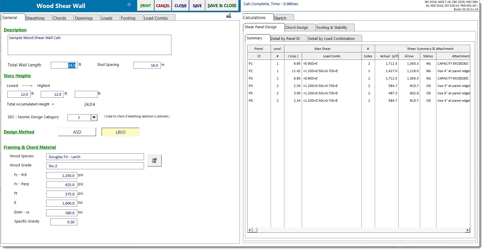
Shear Panel Design
Summary
On a panel-by-panel, level-by-level basis, the Summary tab presents the following information:
Max Shear: Reports the maximum shear force and the load combination associated with that maximum shear force.
# of Sides: Indicates the number of sides to which sheathing has been applied. Will either be 1 or 2.
Shear Summary & Attachment: Reports the actual unit shear, the allowable unit shear, the design status, and the required attachment pattern.
Height/Width Ratio: Reports the actual height-to-width ratio, the allowable height-to-width ratio for Side 1 (Main Sheathing), the allowable height-to-width ratio for Side 2 (2nd Side Sheathing), and notes regarding the status of the height-to-width ratio and any necessary adjustments.
Detail by Panel ID
On a panel-by-panel, load combination-by-load combination basis, the Detail by Panel ID tab presents the following information:
Panel Data: Reports the story in which the panel exists, the distance from the left edge of the overall wall to the left edge of the panel, the width of the panel, the distance from the bottom edge of the overall wall to the bottom edge of the panel, the height of the panel, and the height-to-width ratio of the panel.
Shear Forces: Reports the "Tributary Width" = (Panel Width/∑Panel Widths)*Overall Wall Length, Tributary % = Panel Width/∑Panel Widths, Shear tributary to each panel, panel width, and the maximum unit shear.
Capacity Factors: Reports phi for LRFD designs or the reciprocal of the Factor of Safety for ASD designs, a capacity adjustment factor due to aspect ratio of the sheathing on the Main Sheathing side of the wall, a capacity adjustment factor due to aspect ratio of the sheathing on the 2nd Side of the wall, and a capacity adjustment factor due to the specific gravity of the framing.
Adjusted Allowable Shear: Reports the allowable unit shears for all relevant fastener spacings incorporating any applicable capacity adjustment factors. In situations where two sides of sheathing are being considered, this table will correctly determine the capacity considering both sides of sheathing by applying the rules of 4.3.3.3 and 4.3.3.3.2.
Panel Moment: Reports the moment in the panel.
Chord ID: Reports the identifying labels for the chords at the left and at the right end of each panel.
Detail by Load Combination
On a load combination-by-load combination, panel-by-panel basis, the Detail by Load Combination tab presents the following information:
"Tributary Width" = (Panel Width/∑Panel Widths)*Overall Wall Length
Tributary % = Panel Width/∑Panel Widths
Shear Force = shear tributary to each panel
Chord Design
Chord Data
For each chord in the wall, the Chord Data tab presents the following information:
Location: Reports the Level in which the chord occurs and the distance from the left edge of the overall wall to the chord.
Chord Design: Reports the chord force associated with the controlling design ratio, the load combination responsible for producing the controlling design ratio, then number of chord members required to resist the applied load, the size of the chord member indicated by the user, the governing design ratio, the governing design consideration (tension or compression), and the design status.
Chord Compression Stress: Reports the maximum chord compression force, the load combination responsible for producing the maximum chord compression force, the maximum compressive stress, and the allowable compressive stress.
Chord Tension Stress: Reports the maximum chord tension force, the load combination responsible for producing the maximum chord tension force, the maximum tensile stress, and the allowable tensile stress.
Chord Forces by Chord ID
For each chord in the wall, on a load combination-by-load combination basis the Chord Forces by Chord ID tab presents the following information:
Story: The story in which the chord occurs.
ID: The identification label assigned to the chord.
Axial: Reports the load in the chord due to the sum of applied vertical loads, the load in the chord that can be added or subtracted due to the overturning moment in the panel, the force with the largest (tendency for) tension, and the force with the largest (tendency for) compression.
Chord Location: Reports the distance from the left edge of the overall shear wall to the chord location, the distance from the bottom edge of the overall shear wall to the bottom of the chord, and the distance from the bottom edge of the overall shear wall to the top of the chord.
Footing & Stability
Footing Design Combination Pressures: Reports the maximum factored soil pressures at the left and right sides of the footing, along with the load combination responsible for producing each of those pressures. These are used in the reinforced concrete design calculations for the footing.
Footing One-Way Shear Check: Reports the results of the one-way shear calculation for both ends of the footing.
For footings designed per ACI 318-14 and earlier, the nominal shear strength is ϕ * 2 * λ * sqrt(f'c), where ϕ = 0.75.
For footings designed per ACI 318-19, the nominal shear strength is per the one-way shear strength provisions of §22.5 and Table 22.5.5.1 (as referenced by §13.3.6.1 and §7.5.3.1) and ϕ = 0.75. One way shear capacity assumes no transverse footing reinforcement. Therefore, Av is less than Av,min, and equations (a) and (b) from Table 22.5.5.1 need not be considered.
Footing Bending Design: Reports the results of the flexural analysis and design including recommended reinforcing options to satisfy the required area of steel.
Soil Pressure Combination Pressures: Reports the maximum unfactored soil pressures at the left and right sides of the footing, along with the load combination responsible for producing each of those pressures. Unfactored soil pressures are compared to the allowable soil bearing pressure provided by the user.
Overturning Stability: Reports the overturning analysis performed about each end of the footing including the overturning moment, the resisting moment, the stability ratio, and the governing load combination.
Sketch
The sketch tab provides a convenient graphical view of the shear wall with options to selectively view or hide the following:
•Openings
•Shear Panel callouts
•Chord graphics and callouts
•Panel and opening dimensions
•All loads
 <
<