|
Combined Footing |

|

|

|

|

|
|
|
Combined Footing |
|
|
|
|

|
Combined Footing
|
Combined Footing |
|
|
|
|
|
|
|
Combined Footing |
|
|
|
|
|
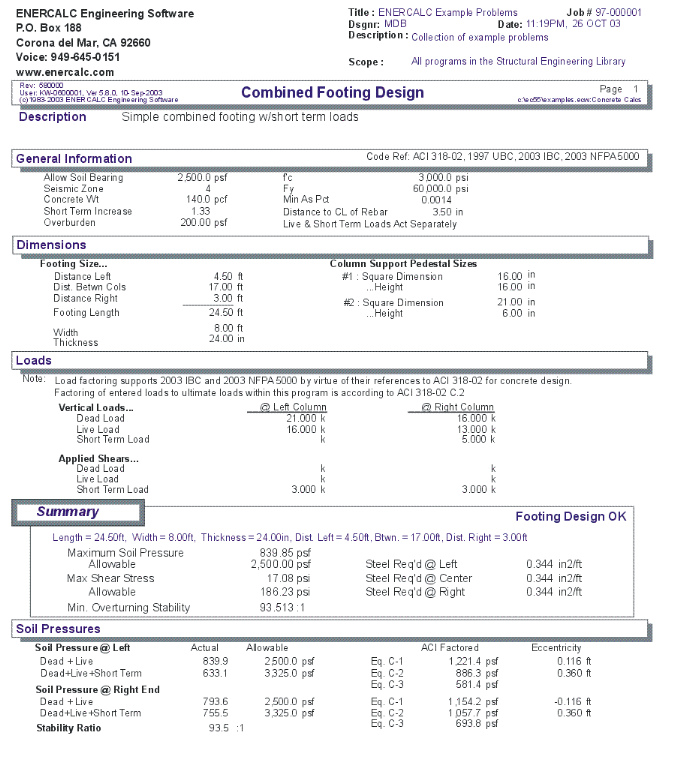
This program provides design and analysis of rectangular footings supporting two columns applying axial load, lateral shear, and bending moment forces. The program is ideal for footings supporting braced frames (short-term uplift at one end) and for eccentrically loaded footings which need to have semi-uniform soil loading patterns.
Each column can apply dead, live, and short term loads to the footing, can have their own depth and width dimensions, and can be located at any distance apart and from the footing ends. The columns must lie on the footing centerline along the longer axis .
In addition to the column loads, footing weight and overburden loads are added. A typical feature allows you to specify a seismic zone number from 0" through 4", 0" indicating wind loads and 1" through 4" being used by the program to control seismic load factoring.
Footing projections on either side of the columns, footing width, and footing thickness can be easily modified to design a footing to satisfy soil pressure, shear, bending, and overturning stability requirements.
The program provides complete analysis and design results by combining all loads using factored ACI load combinations 9-1, 9-2, and 9-3, including one way shears, two way shears, service and factored soil pressures, and bending moments and reinforcing.
Basic Usage
| • | Allowable Soil Pressure and Short Term Factor specify the maximum soil bearing pressure allowed for static (DL+LL) and short term (DL+LL+ST) load combinations. Seismic Zone should be set to 0" if short-term loads are due to wind, and 1" through 4" if seismic. If you wish to Combine Live Loads with short term loads, all short term calculations will use DL+LL+ST (typical seismic design uses DL+ ST only). |
| • | Concrete Weight and Overburden will be added in as dead loads during the analysis. (Overburden will be applied to the area above the footing, less the area specified for column size). Minimum As % will be used as an absolute minimum when determining reinforcing requirements. |
| • | Axial loads, lateral shears, and moments with dead, live, and short-term components can be applied to each column. Although these loads act along the footing centerline, they can be positive or negative, allowing design of footings supporting braced frames. |
| • | Sign Conventions are as follows: |
| • | Positive Axial Loads act downward. |
| • | Positive Lateral Shears act to the right, creating greater soil pressure |
| • | at the right side of the footing. |
| • | Positive Moments act clockwise, creating greater soil pressure at the |
| • | right side of the footing. |
| • | Footing Dimensions can be specified for the distance left of column #1, right of column #2, and the distance between columns. These are added to give the total footing length. Footing width, thickness, and rebar clear cover complete the specifying of footing dimensions. |
| • | Calculating the program will determine the actual service and factored soil pressures, moments and shears, and required reinforcing. You can then modify footing sizes and reinforcing to obtain optimum designs. All three ACI load factor combinations 9-1, 9-2, and 9-3 are evaluated simultaneously. |
Unique Features
| • | This program easily sizes a footing supporting two loads with moments and lateral shears, and gives maximum and minimum soil pressures, one and two way shears and bending moments evaluated for both ends of the footing. |
| • | Accepts both static and seismic/wind loads, and evaluates soil pressure for both. |
| • | Footing size can be easily varied to optimize design. |
| • | Overburden and footing weight are taken into consideration. |
| • | Short-term load can be specified as either seismic or wind. |
| • | User may specify whether or not live loads act during short term. |
| • | Distance between columns is divided into 250 increments for calculation of maximum moments. |
Assumptions & Limitations
| • | Both columns must lie on the footing centerline along one axis. |
| • | Beam on Elastic Foundation effects of soil are not considered. This analysis assumes that soil pressures will be linear under a rigid footing. |
Example
The data entry for this example is shown in the screen captures that accompany the Data Entry Tabs and Results & Graphics Tabs sections to follow.
Data Entry Tabs
This set of tabs provides entries for all input in this calculation. While you are entering data and switching between these tabs you can view the desired resulting information on the tabs on the right-hand side of the screen (calculated values, sketches, diagrams, etc.). A recalculation is performed after any entry data is changed. After each data entry you can view the results on the right-hand set of tabs.
General Tab
Allowable Soil Pressure
Enter the maximum allowable soil bearing pressure for static loading.
Distance Left
This is the distance the footing extends on the left side of the footing. It is measured from the centerline of the left side column to the edge of footing.
Between Columns
This is the separation between columns, measured between the column centerline's.
Distance Right
This is the distance the footing extends on the right side of the footing. It is measured from the centerline of the right side column to the edge of footing.
Footing Length
The total length of the footing which equals Distance Left + Between Columns + Distance Right.
Width
Width of the footing
Thickness
Thickness of the footing
Column Support Pedestal Sizes
These dimensions define the distances that will be used to compute moments and shears. The edge of this area defines an assumed solid column at which moments will act. Distances of d and d/2" will be added to the edge location for calculation of shear forces. Overburden weight is not applied to this area.
Design Data Tab
Seismic Zone
This entry is used to control overall ACI load factoring. When wind loads generate the short-term forces, enter a 0" here. When seismic loads generate the short-term loads, enter 1" through 4" here to indicate the UBC seismic zone. When zone 3 or 4 is used, the special load factoring provisions of the UBC are applied.
Include Live Load w/ Short Term Loads
This entry instructs the program when to include live load with short-term loads. Typically, wind load analysis will include live load, while short-term loads due to seismic forces are not combined with live loads.
Short Term Increase
If a short-term increase in soil pressure will be allowed, enter the multiplier here.
f'c
Allowable compressive stress for the concrete.
Fy
Allowable yield stress of the reinforcing steel.
Min. As %
Enter the minimum percentage of steel reinforcing that you wish the program to use when determining required reinforcing area.
Distance to Centerline of Rebar
Enter the distance from the top or bottom of the footing to the centerline of the reinforcing. This will be subtracted from the footing thickness to calculate rebar d distances when determining required reinforcing and shear depths and distances.
Concrete Weight
By entering a non-zero number here, the weight of the footing will be included in soil bearing pressure calculations.
Loads Tab
Vertical Loads
The footing may support two columns transferring axial, shear, and moment loads to the footing. Each of these columns must lie along the centerline of the footing, but may be positioned at any location along the footings length. Axial Each axial load can have dead, live, and short term components.
Applied Moments
Each column may apply a moment to the footing, consisting of dead, live, and short-term components. Positive moments will apply a Clockwise torque to the footing (opposite the typical direction for right-hand-rule). Positive moments will increase the soil pressure at the right end of the footing.
Applied Shears
Each column may apply a lateral shear at the top of the footing, consisting of dead, live, and short-term components. Positive shears will apply a force to the right. Positive shears will be applied at a vertical eccentricity equal to the Footing Thickness and the resulting moment will increase the soil pressure at the right end of the footing.
Overburden
This is a general load that you may input to apply an additional uniform area load on the top of the entire footing. This load is also applied where the column dimensions are defined and so will be slightly conservative.
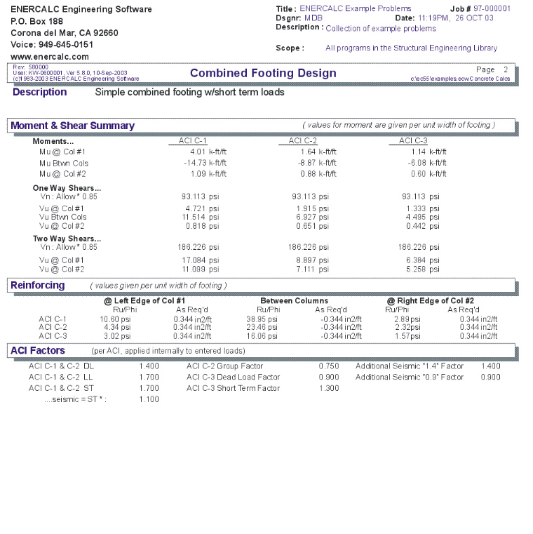
ACI Factors Tab
This tab specifies the load factors to be used by the program when calculation the factored dead, live, and short term loads to be used in the internal load combinations for determining Mu & Vu.
Results & Graphics Tabs
This set of tabs provides the calculated values resulting from your input on the "Data Entry Tabs". Because a recalculation is performed with each data entry, the information on these tabs always reflects the accurate and current results, problem sketch, or stress/deflection diagram.
Results Tab
This tab gives the calculated governing values of maximum soil pressure, footing shear, and the minimum overturning stability ration for the footing considering all applied loads and load combinations.
Overturning Stability
The overturning stability ratio for the footing is calculated considering all applied moments, shears, vertical loads, footing weight, and soil weight for both static and short-term cases.
For this value, both sides of the footing are used as a reference point for calculation of overturning ratios and the smaller value is displayed, representing the minimum factor of safety. "999" indicates there is no overturning on the footing, or the ratio is so great as to be meaningless.
As Req'd
Required area of steel is calculated by:
| • | Using the maximum Mu to determine the required steel percentage |
| • | Comparing the required steel percentage with 200/Fy. If required is greater than 200/Fy, then required is used. If the required percentage is less than 200/Fy, the required is multiplied by 1.33 and that result compared with 200/Fy, and the lesser value used. |
The resulting percentage calculated above is compared with Minimum Steel % the user entered, and the maximum of those values multiplied by the footing area to determine required area. If As = 999, required steel exceeds 0.75 * Rho Balanced.
Results / Soil Pressure Tab
Static Soil Pressures
For each end of the footing, the axial loads, shears, moments, overburden, and footing weight are applied to calculate the static soil pressures. Dead and live load forces are included in this calculation, no short term loads. These pressure values are compared to the basic allowable soil bearing pressure.
Short Term Soil Pressures
This is similar to the "Static" calculation, except short term load is always included, and live load is included only if Combine LL & ST is set to YES.
Unfactored Soil Pressures
Service level soil pressures are the resulting soil pressures BEFORE any ACI load factors are applied, and are used to determine compliance with allowable soil bearing pressures. Allowable pressure for "Static" conditions is a simple restatement of the Allowable Soil Pressure entered at the top of the program. Short term allowable pressure equal the static allowable multiplied by the "Short Term Factor".
ACI Factored Soil Pressures
For both the left and right end of the footing, ACI equations 9-1, 9-2, and 9-3 are used to factor the various combinations of dead, live, and short term loads to arrive at the factored soil pressures presented here. These pressures are used to calculate moments and shears in the footing, both at each end and between supports.
Results / M & V Summary Tab
Moments
Mu for ACI Equation The bending moments for both static and short-term cases are listed here. Evaluation of bending moments include factored soil pressure (and its variation in intensity under the footing, even in cases where the eccentricity lies outside the kern), footing weight, and overburden weight. When values appear as negative, indicates that steel reinforcing must be placed in the top of the footing.
The maximum moment between columns is evaluated by finding the maximum moment at 100 points. Variation in soil pressure, footing weight, soil weight, applied moments, and moments induced by horizontal shears applied to the columns are all considered in the maximum moment calculation.
For Mu at Column #1 and Column #2, the moments are induced from upward soil pressure applied to the cantilever portion of the footing, downward force from overburden and footing weight.
One-Way Shear
Using the maximum factored soil pressures presented earlier, the maximum one way shear stress at a vertical plane a distance d away from the Equivalent Column face. The vertical depth used for shear area equals footing thickness minus Rebar CL To Soil. Allowable one-way shear stress is calculated as : 2 * f'c½
2-Way Shear
The maximum two-way shear stress in taken on four vertical planes a distance d/2 away from the Equivalent Column face. The vertical depth used for shear area equals footing thickness minus Rebar CL To Soil. Allowable two-shear stress is calculated as : 4 * f'c½
Results / Reinforcing Tab
This tab summarizes the required reinforcing for the three important locations on the footing:
Due to moments created at the left side of the left column due to upward soil loads in the left footing projection.
Moments in the footing between the columns due to upward soil pressure.
Due to moments created at the right side of the right column due to upward soil loads in the right footing projection.
Ru/Phi
This is the resisting modulus required by the footing section which is MU/(b * d^2 * Phi)
As Required
This is the area of steel required per foot of footing WIDTH at the location.
Sketch Tab
This tab provides a sketch of the beam with loads and resulting values shown. Using the [Print Sketch] button will print the sketch in large scale on a single sheet of paper.
Diagrams Tab
This displays a moment, shear, and deflection diagram for the beam with the applied loads and end conditions. Note the two tabs...."Graphic Diagram" and "Data Table". The Data Table tab provides the entire internal analysis at the 1/500th points within the beam.
Printing Tab
This tab allows you to control which areas of the calculation to print. Checking a box will signal that the information described by the item will be printed. However, if there is no information in for a particular selection it will not be printed. So these checkboxes are best described as "If this particular area of the calculations contains data then print it".
Sample Printout