|
Composite Steel Beam |

|

|

|

|

|
|
|
Composite Steel Beam |
|
|
|
|

|
Composite Steel Beam
|
Composite Steel Beam |
|
|
|
|
|
|
|
Composite Steel Beam |
|
|
|
|
|
This program provides design and analysis of AISC steel sections acting compositely with a concrete slab interlocked along its compression flange. Factors provided for in the program include:
| • | The concrete slab can be either full depth or cast over formed steel decking, with rib orientation perpendicular or parallel. |
| • | The concrete slab may extend past one or both sides of the beam. |
| • | An optional steel plate may be attached below the bottom flange to allow strengthening of existing beams. |
| • | When formed steel deck is used, stud capacity reduction factors are automatically calculated. |
| • | Normal or lightweight concrete may be used for both design and deflection calculations. |
| • | Shear connector requirements are given at six locations along the span, based on shear variations. |
| • | Construction Only loads can be used to represent formwork that will be removed after curing to allow full composite action. |
| • | Both shored and unshored construction techniques are analyzed by the program. |
You can load the simple span beam with up to 17 distributed loads and 15 point loads. Distributed loads can be full or partial length, and all loads are separated between:
| • | Loads applied during and after construction (Dead Loads). |
| • | Loads applied after 75% concrete curing (Live Loads). |
| • | Loads applied ONLY before 75% curing (Construction Only). |
Both shored and unshored conditions are examined for stresses and deflections. The program determines deflections for both shored and unshored conditions. Also, the user may specify different concrete properties for use in determining section properties for deflection calculations, in addition to transformed section properties for strength analysis.
The program can use any section from the internal AISC databases. Also provided is automatic member selection using criteria the user has specified.
Basic Usage
| • | Enter Beam and Slab Data |
| • | Enter the beam span to be used for calculation of moments and deflections, and the spacing between beams to be used for calculation of effective slab width. |
| • | Enter the total slab thickness (distance from top flange to final surface). When metal deck is used, enter the data to describe the deck ribs. This will be used to calculate transformed section properties. |
| • | Location should be set to 1" when the concrete slab only extends past one edge of the beam. To achieve the greatest economy of design, Partial can be set to YES to enable calculation of the minimum number of connectors allowable to achieve the minimum interlock to satisfy stress requirements. |
| • | Enter Design Data. This sections allows you to enter the allowable material strengths for beam, slab, and shear connectors. Stud height will only be used when metal deck stud capacity reductions are required. |
| • | Applied Loads : |
| • | Uniform loads apply to the entire span. Trapezoidal loads MUST BE POSITIVE , but can be of any starting and ending magnitude and any start or end location. Point loads may applied anywhere on the span. |
| • | Loads Applied Before 75% Curing are dead loads that will be applied to the beam for the duration of its life. If the beam is shored, the dead load will be applied to the composite section, not the beam alone, since all loads will be supported by the shores until curing has reached 75%. |
| • | Loads Applied After 75% Curing are typical live loads applied after the concrete has cured. |
| • | Loads Applied During Construction are applied to the beam only during curing, and are taken out of the calculations for final, long term stresses. When the beam is shored, this type of load has no meaning. |
| • | Section Properties can be entered by using the built-in section property databases. Please see the following two sections on using this capability. |
| • | Reviewing Forces and Stresses. In the Summary section of the worksheet the actual and allowable bending and shear stresses will be listed. Also, various moments, shears, deflections and reactions due to six load placement conditions will be given. |
Unique Features
| • | User may have the program automatically select the lightest section from the AISC section database. |
| • | An additional steel plate can be added to the bottom flange of the beam to strengthen existing sections. |
| • | The program allows the use of lightweight concrete. Different n values are calculated to determine section properties for strength design and for deflection calculations. |
Steel Section Database
Built into the software is a complete database of common rolled sections available from various mills in the United States. On each tab labeled #1, #2, etc. there will be a button that looks like this:
![]()
This button displays the steel section database as shown below.
On this window there are various controls and options.....
Steel Database : Allows you to select between several common shapes databases.
Section Type to Display: Allows you to select which steel section designation to display in the list. These shapes conform to the American Institute of Steel Construction shape designations. To make your selection simply move the mouse over the letter(s) and when the highlight activates left-click once with your left mouse button.
Depth Range: This item allows you to specify depth limits to be used for selecting which sections to display in the list. When the checkbox to the left is not checked the selection wording and entries will not appear and all sections will be displayed. These dimensions are compared to the "Depth" dimension of the sections.
Class Range : This item allows you to specify the limits in "Depth Class" to be displayed in the table. The "Depth Class" of a section is the first numeric number in the sections name. For instance a wide flange W14x22 is in depth class "14". a channel C9x15 is in depth class "9", and a L5x3x1/4 is in depth class "5".
Equal & Unequal Legs : These two buttons appear when you have selected section type "L" which are single angles. The limit the display of the list to angle with equal dimension or unequal dimension sides.
Equal Legs, Long Leg Vertical, Short Leg Vertical: These three buttons appear when you have chosen to display section type "LL". These control the display of sections between pairs of angles with both sides of equal length, of unequal side length angles paired with the LONG side together, and unequal side length angles paired with the SHORTside together.
Square & Rectangular Tubes: These two buttons appear when you have chosen section types TS or HSS-T. These are square tubular sections. You can choose to display only square tubes or alternately tubes with unequal sides.
Sort Tabs for Database Table : Immediate above the database list of sections you will see tabs looking like this....
When selected each tab will sort the list in the order described by the text on that tab.
Sort order : These two buttons allow you to chose the list order of the sections. The sorting order will be according to the sort tab selected and shall be in ascending or descending order.
Database Table Itself : The main area on the window will be where the steel sections are displayed as a result of all of your choices as described above.
[Select] : This button is displayed when you have clicked on the [Section] button when you press [Select] the section in the list that is currently highlighted will be selected and the name and data brought into your calculation.
[Insert]: Use this button to add a steel section to the database. When pressed you will see the following window:
The only really important item to enter is the "Type" item. This specifies what standard rolled section type your section is. This item is used internally by the program to decide which stress analysis method to use for determining the sections allowable stress, how to consider unstiffenned elements, and many other code checking items.
[Change]: Will display the same window as above but allow you to change section properties.
[Delete] : Will enable you to delete sections. Note: No sections in the supplied database can be deleted. Only Sections that you ad can be later deleted.
[Cancel]: Exit the steel database window.
ASD Design Modes
Allowable Stress Design as specified by the American Institute of Steel Construction is provided by this program. Only screen captures and descriptions for ASD are presented in this book. Check these locations for electronic media:
| • | Latest Adobe Acrobat PDF documentation file here: ftp://208.36.30.226/sel5.pdf. |
| • | Latest Windows Help system file here : ftp://208.36.30.226/enercalc.hlp. |
| • | Internet HTML help documentation presented as web pages at www.enercalc.com/sel_help. |
Example
The data entry for this example is shown in the screen captures that accompany the Data Entry Tabs and Results & Graphics Tabs sections to follow.
Data Entry Tabs
This set of tabs provides entries for all input in this calculation. While you are entering data and switching between these tabs you can view the desired resulting information on the tabs on the right-hand side of the screen (calculated values, sketches, diagrams, etc.). A recalculation is performed after any entry data is changed. After each data entry you can view the results on the right-hand set of tabs.
General Tab
All of the information for the beam design except for loading is entered on this tab.
Beam Span
The beam span length is used for determination of effective flange width and evaluation of moments and shears.
Beam Spacing
Enter the center to center spacing for the beam to be used to determining effective flange width.
Beam Location
This specifies whether the beam is an interior beam with slab extending a distance of (Trib Width)/2 on each side of the beam. If beam to be designed will have slab on only one side select "Edge". If the slab extends on both side select "Center". This item will be used to determine the effective flange width for the composite section.
Partial Composite Action
Designer may choose whether or not to use a reduced shear force if transformed section modulus supplied is greater than that required. If user does not use partial action, shear force calculated from AISC equations 1.11-3 & 1.11-4 is used to determine connector requirements.
Steel Section
This is where you specify the rolled steel section to be used in the design. There are two ways to enter & specify the section.
| • | Use the [Section] button to retrieve the section from the built-in steel database. See the description given previously for more information. |
| • | Type in the section name and the program will automatically look through the database for a match. Upper or lower case is fine. If found the name and numeric section properties will be retrieved into this calculation. The numeric properties will be seen on the "Section Properties" tab. |
Slab Thickness
This is the TOTAL THICKNESS of the structural material over the top of the beam. If you are using metal decking with concrete fill this thickness is the deck height plus concrete topping.
Stud Diameter
The diameter of the shear studs is measured at the base, not the maximum head diameter. This dimension is used to calculate stud capacities using internal tables and reduction equations if metal deck is used.
Stud Height
The stud height is used to calculate stud capacities when metal decking is used.
Metal Deck Notes
When metal decking is used, the program automatically decides what concrete area is to be used. When the deck ribs are oriented parallel to the beam, the total actual concrete area (based on the rib dimensions and effective flange width) is used for calculations. The center of area is adjusted for the area distribution as it occurs (it varies due to ribs). When ribs are perpendicular to the beam, only the concrete area between the top of the slab and top of the ribs is used.
Deck Rib Height
Rib height is the total depth of the metal decking (distance from the top flange of the beam to the top surface of the decking). Used along with Rib Spacing and Rib Width to determine the net concrete area for composite section properties.
Rib Spacing
Center to center spacing of the metal deck ribs. This is used with Rib Height and Rib Width to determine the net concrete area for composite action.
Rib Opening Width
When viewed from above the decking, this represents the width of the CONCAVE section of the metal deck which will be filled with concrete. Used with Rib Height and Rib Spacing to determine the net concrete area for composite action.
Rib Orientation
This entry indicates if the metal deck ribs are parallel with the steel beam. If parallel, the transformed section properties will include the concrete area within the Rib Opening Width areas. If perpendicular, that area will not be used. Also, shear stud reduction factors will be used.
Fy
Indicates yield strength of structural steel to be used. For unshored construction, .89 Fy is used as a maximum allowable steel stress for service loading conditions.
f'c
Indicates design strength of concrete to be used. Allowable compressive stress for design at top of slab is limited to .45 f'c.
Concrete Density
Density Unit weight of concrete, and is used to determine the n ratio to be used in calculation of transformed moment of inertia, to be used in deflection calculations.
Elastic Modulus
Although rarely does this need to be changed, enter the elastic modulus of the steel material.
General Information About Loads
| • | Negative loads should not be entered. Negative moments will cause tension in the concrete, which is not acceptable in this program!! |
| • | For SHORED conditions, no load is applied to the steel beam alone. Upon removal of the shores when 75% curing has been attained, all load is transferred to the full composite section. Construction Only loads are meaningless and never used. |
| • | For UNSHORED conditions, the steel beam alone supports the BEFORE 75% loads and Construction Only loads. You Must Insure Adequate Lateral Support Of The Compression Flange So Lateral Buckling Does Not Occur. When the shores are removed, the Construction Only loads are assumed to be removed, and the full composite section takes live loads. Theoretically, when the Construction Only load is removed, the beam deflection decreases, thus causing tension in the concrete. This Effect Is Ignored By The Program. |
Dead Loads Tab
"Dead Loads" in this program are Loads Applied BEFORE 75% Curing. These loads are considered typical dead loads, placed on the beam for its entire life.
Auto Calc Beam Weight uses the area of the beam and standard density of steel PLUS the area of the slab (considering metal deck ribs if used) and entered concrete density to add in the total beam weight as a uniform dead load on the span. (This is done internally).
Load locations are measured from the left support going to the right.
Live Loads Tab
"Live Loads" in this program are Loads Applied AFTER 75% Curing. These loads are considered typical live loads that may or may not be applied to the span
Construction Loads Tab
These loads are only considered for UNSHORED construction. These loads cause dead load stress in the STEEL SECTION ONLY. When the concrete has attained 75% curing, these loads are assumed to be removed and only the other two types of loads will be used. These loads are ignored for shored construction.
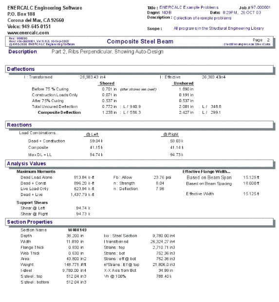
Section Properties Tab
This secondary tab is where the steel section properties are listed. The properties shown here are used for the calculation. Also given are the calculated transformed section properties for the beam
Optional Bottom Flange Cover Plate
These two entries allow you to add a steel plate to the bottom flange of the beam. Many times existing beams are strengthened by raising up the beam to release loads, welding on a plate to the bottom flange, and then releasing the beam so that the cover plate comes into play creating different transformed section properties.
I-Steel
Moment of inertia of the entire steel section (with added cover plate), but not including concrete area.
S-Steel-Top
Section modulus of steel section with added cover plate (not including concrete area), for calculation of top of beam stresses.
S-Steel - Bottom
Section modulus of steel section with added cover plate (not including concrete area) for calculation of top of beam stresses.
I-Trans Effective
Transformed moment of inertia of the section when concrete slab is combined with the steel section (and optional cover plate). Used to determine the transformed section modulus and for live load deflection calculation. If partial composite action has been specified, this value is adjusted for the effect of partial composite action
Ieff = Isteel + [(Itrans-Isteel) * (V'h/Vh)½]
Where V'h is the adjusted shear stress based on the number of shear connectors used. If partial action has not been specified, the full value of Icomposite is used.
S-Trans Top
Transformed section modulus at top of steel beam. This is used to calculate n*STR for use in calculating concrete stresses.
S-Trans Bottom
Transformed effective section modulus including concrete area and optional cover plate. Also used to determine partial shear force when S-tr required is less than S-tr supplied for calculation of required number of shear connectors.
Actual STR Effective
This is the actual STRANS being used. The effective transformed section modulus is the calculated STRANS modified for partial composite action (i.e. for a reduced number of shear studs).
n * S-tr Top
Modular ratio Es/Ec times the transformed section modulus at the top of the composite section (top of the slab). Used to determine the service load concrete stress (which should be less than .45 f'c).
X-X Axis Bottom
Distance measured upward from the bottom of the steel section (not bottom of the optional cover plate), to the neutral axis of the transformed section. Used only to determine transformed section modulus of the steel section.
V-Horiz @ 100%
Horizontal shear, calculated as the minimum of AISC equations 1.11-3 and 1.11-4:
0.85 * f'c * Ac/2 -or- AS * Fy/2.
Used to calculate required shear connectors unless partial composite action is allowed.
Results & Graphics Tabs
This set of tabs provides the calculated values resulting from your input on the "Data Entry Tabs". Because a recalculation is performed with each data entry, the information on these tabs always reflects the accurate and current results, problem sketch, or stress/deflection diagram.
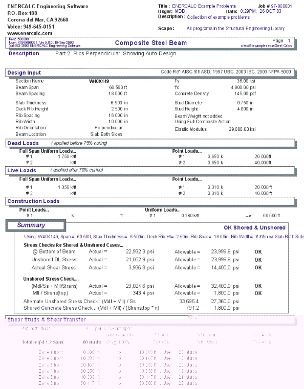
Results / Results Tab
Stress Checks for Shored & Unshored Cases
The stress checks in this area MUST BE SATISFIED if the beam is to be used at all. These are basic stress checks for composite beams.
@ Bottom of Beam
This value is the maximum stress if both loads applied after 75% curing (but not construction only loads) are applied to the fully composite section.
Stress = (MDL + MLL)/ STRANSFORMED
Unshored Dead Load Stress
This stress results from applying Loads before 75% and Construction Only loads to the steel beam only. This is the maximum moment the steel beam will have to support by itself. (You need to check the beam for lateral buckling and compact section criteria).
Stress = MDL/ SSTEEL
Actual Shear Stress
This is the maximum shear stress in the beam web from all combinations of applied loads.
Unshored Stress Check
The stress checks in this area MUST BE SATISFIED if the beam can be constructed without shoring. This section provides information checking whether or not the section can be constructed as an unshored member, (1.35+.35MLL/MDL)*SS
This value is the maximum allowable Strans that can be allowed to determine unshored stresses. This equation effectively limits the steel beams tension stress to 0.89 Fy. You will notice that the stress check (below) compares the actual maximum unshored steel stress against 0.89Fy.
(Mdl / Ss + Mll / Strans )
This equation calculates the maximum steel stress at the bottom of the member for unshored construction. This stress must not exceed 0.89Fy.
Mll / Strans(top)
This equation calculates the maximum concrete compressive stress for unshored construction.
Alternate Unshored Stress Check
This check compares the load combination (Mdl + Mll) / Ss, the total moment divided by the steel section modulus. If this stress is OK, the applied loads will not overstress the steel section acting alone, therefore composite action isn't really being taken advantage of (except for deflection control).
Shored Concrete Stress Check
(MDL + MLL )/(STR:TOP*n) : This equation calculates the maximum concrete compressive stress for shored construction.
Results / Shear Studs Tab
This section gives details of the shear connector requirements, and allows you to specify the actual number of shear connectors used when examining an existing beam.
Actual #Of Shear Studs Used
This is an optional entry, and can be used when you want to analyze an as built beam. If this entry is 0", the program calculates the required number of studs, and the shear stud spacing values reflect that force. If you enter the actual number of studs per ½ span in this location, that number will be multiplied by the allowable shear connector capacity and the result shown as Shear Force Used For Connector Design".
Vh @ 100%
This is the maximum horizontal to be resisted (by code), calculated as the minimum of AISC equations 1.11-3 and 1.11-4:
0.85 * f'c * Ac/2 -or- AS * Fy/2.
Vh Minimum
When partial composite action has been allowed, this value is Vh @ 100% adjusted by the formula:
V'h=Vh*[(SREQ'D-SSTEEL)/(STRANS-SSTEEL)] 2
This force is the minimum force which the connectors should be designed to resist. If no entry has been made for OPTIONAL ACTUAL STUDS....., the shear stud spacings will be listed for this value, otherwise Shear Force Used For Connector Design (below) will be used to determine spacings.
Shear Force Used For Connector Design
This is either the maximum value of either Vh Minimum or Vh @ 100% adjusted for partial composite action (see above), or if a non-zero number has been entered for Actual Number of Shear Studs, that value is multiplied by allowable connector capacity and used.
Total Studs Required
The shear force is divided by the individual connector capacity to determine the number of connectors required between the point of maximum shear and zero shear. If partial action has been chosen, the adjusted shear force is used, otherwise the result of AISC formula 1.11-3 & 1.11-4 is used.
Shear Connector Table
This table lists the shear connectors required between the distance ranges shown.
Results / Deflection Tab
Deflections for both shored and unshored conditions are listed. The deflections are calculated for various combinations of loads at 250 points along the span, and the maximums listed.
I-Transformed
This is the overall transformed moment of inertia before any modification has been made for partial composite action.
I-Effective
Transformed moment of inertia after allowance has been made for partial composite action.
Results / Reactions Tab
This tab gives the support reactions for various combinations of dead, live and construction loads.
Results / Moments, Shears, etc. Tab
This tab displays a breakdown of the moments & shears for the various combinations of load types.
Const. Only
This values is due to Loads applied Before 75% and Construction Only Loads being applied to the beam.
Const. + Composite
This values is due to Loads applied Before 75% and Loads applied After 75% being applied to the beam.
Max. Shear
This value is the maximum shear at each end due to all combinations of loads.
Effective Flange Width
Based On Span
Center Beam Location = SPAN/4
Edge Beam Location = SPAN/12+Bf
Based on Beam Spacing
Center Beam Location = BEAM SPACING
Edge Beam Location = (BEAM SPACING + Bf)/2
Effective Width
The effective width is the minimum of the above three equations.
Sketch Tab
This tab provides a sketch of the beam with loads and resulting values shown. Using the [Print Sketch] button will print the sketch in large scale on a single sheet of paper.
Diagrams Tab
This displays a moment, shear, and deflection diagram for the beam with the applied loads and end conditions. Note the two tabs...."Graphic Diagram" and "Data Table". The Data Table tab provides the entire internal analysis at the 1/500th points within the beam.
Printing Tab
This tab allows you to control which areas of the calculation to print. Checking a box will signal that the information described by the item will be printed. However, if there is no information in for a particular selection it will not be printed. So these checkboxes are best described as "If this particular area of the calculations contains data then print it".
Sample Printout