|
Horizontal Plywood Diaphragm |

|

|

|

|

|
|
|
Horizontal Plywood Diaphragm |
|
|
|
|

|
Horizontal Plywood Diaphragm
|
Horizontal Plywood Diaphragm |
|
|
|
|
|
|
|
Horizontal Plywood Diaphragm |
|
|
|
|
|
This program provides analysis and design of horizontal rectangular plywood diaphragms subjected lateral loads from wind or seismic forces.
This program calculates nailing requirements and shear values using UBC Table 23-I-J-1, including blocked and unblocked diaphragms. For conditions where high diaphragm loads create shears exceeding those available from the UBC table, you can use the High Load Plywood Diaphragm program, which uses ICBO Report #1952 for diaphragm design using 23/32" plywood applied according to the reports requirements.
Loads due to diaphragm self weight and lateral loads applied to the diaphragm boundary are allowed. To analyze diaphragms subjected to wind loads only, specify diaphragm weight as zero and seismic factor as 1".
Up to four partial or full length uniform loads can be applied to the diaphragm boundary in both the North-South or East-West direction. The partial length ability allows you to model seismic wall weight or wind loads on portions of the building with different tributary areas.
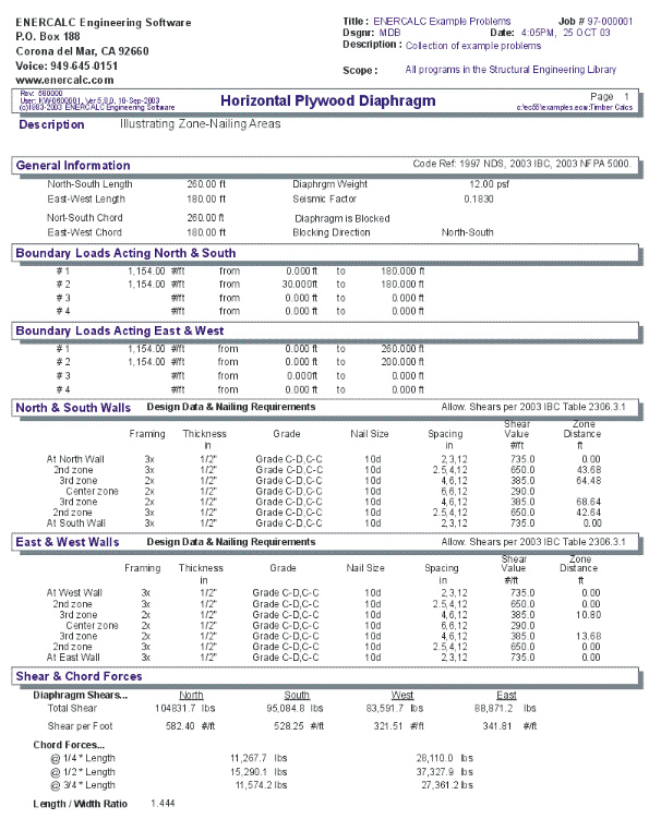
The program calculates total shear and unit shear for each of the four sides of the diaphragm, chord forces at 1/4 points, and will determine diaphragm nailing density and cut-off requirements for various diaphragm shear capacities.
A unique feature of the program allows the user to vary the nail size, plywood thickness, plywood grade, and member size and have the allowable shear values for the particular specification recalled from an internally stored table. The program will then calculate the minimum nail density reduction distances from each wall, based upon the actual shear variation across the diaphragm.
Basic Usage
| • | Before using the program, establish a North/South axis system to use for reference. This will make data entry and interpretation of results much easier, since all program input and output makes reference to such a layout. |
| • | Diaphragm Lengths & Chord Separations. Enter the length and width of the rectangular diaphragm, then enter the chord separations. We have provided the ability to separate chord distance from building dimensions to allow use of beam lines as chords, typically needed when the exterior walls have discontinuities. |
| • | Diaphragm Weight only needs to be entered when seismic forces are being used, and will be multiplied by Short Term Factor before generating lateral loads. For wind analysis, set this item equal to zero. |
| • | Short Term Factor will be applied to diaphragm weight and applied boundary loads to generate lateral forces. For wind analysis, this should be set to 1". For seismic analysis, enter the overall structural seismic factor. |
| • | Blocked/Unblocked and Load Direction are used when retrieving allowable diaphragm shear values from the internally stored UBC tables. |
| • | Applied Boundary Loads are used to transmit wind or seismic forces to the diaphragm. For wind analysis , the wind load on the tributary portion of the exposed structure is entered. For seismic analysis , enter the actual tributary weight before applying a seismic factor. |
| • | Review Nailing Requirements. This table is used to iteratively design the diaphragm on a ZONE basis. Each row represents the diaphragm construction for the nail spacings listed under Spacing Req'd. The values YOU enter for Framing Size, Plywood Thickness, Plywood Grade, and Nail Size will be used to retrieve an allowable Shear Value from the internal UBC table. The Zone Distance indicates how far from the wall that particular construction and nail spacing must be used. |
| • | If Zone Distance is "0" , then that particular nail density (diaphragm construction) is NOT NEEDED . The next lower nail spacing/construction type should be used at the wall. When no shears exceed the allowable for 6", 6",12" spacing, all Zone Distances will be "0", and the "typical" nail density/ construction type should be used. |
| • | Refine Plywood Values and recalculate as required so that the nail density and shear values can adequately resist the shears. |
| • | Print or Save the data for the worksheet, Reset all values to zero to start a new problem, or use the Access Menu to choose another program. |
Unique Features
| • | Allows quick design of rectangular plywood diaphragms with self and varying length applied loads. |
| • | User may vary chord spacing according to needs and obtain chord forces at 1/4 points of span (or other locations as specified). |
Example
The data entry for this example is shown in the screen captures that accompany the Data Entry Tabs and Results & Graphics Tabs sections to follow.
Data Entry Tabs
This set of tabs provides entries for all input in this calculation. While you are entering data and switching between these tabs you can view the desired resulting information on the tabs on the right-hand side of the screen (calculated values, sketches, diagrams, etc.). A recalculation is performed after any entry data is changed. After each data entry you can view the results on the right-hand set of tabs.
General Tab
North/South Length
This defines the North-South dimension of the diaphragm. This length will be used to:
| • | Calculate the total lateral load due to the diaphragm's self-weight (multiplied by seismic factor). |
| • | Used to divide the total shear at the east and west walls due to north-south forces, resulting in a shear per foot value which the diaphragm must resist. |
East/West Length
Please see the description above, except reverse all the directions.
Distance Between Chords
Normally, the user will enter the same values here as the diaphragm lengths. When the distance between the chords is more or less than the length, enter these new distances here, and they will be used to determine the chord forces. An example where this might be necessary is when a building has a very broken up side and there is no way to run a continuous tension chord member along the wall. In those cases you would use a line of beams with heavy straps tying them together when interrupted at a connection or other break,
Length/Width Ratio
Equals Maximum Dimension/Minimum Dimension(most codes limit to 4:1).
Diaphragm Weight
Defines the actual self-weight of the plywood diaphragm (before any adjustments for seismic factor). This value will be multiplied by the Length, Width and Seismic Factor to determine the total lateral force acting. This weight is in addition to the Applied Boundary Loads as detailed below.
SET THIS ENTRY TO 0" FOR WIND LOAD ANALYSIS. Enter the wind loads in the section titled Applied Load in N/S & E/W Direction.
Seismic Factor
Working stress level seismic factor will be applied to the diaphragm self weight and boundary loads to determine the total lateral force acting on the diaphragm. Remember, enter all lateral loads without any factors applied.
Various codes specify this value in either "Working Stress" or "Factored Loads". For instance the recent UBC and IBC codes use a higher "factored" load factor that needs to be divided by 1.4 before entering it here.
If you are using the program to analyze a diaphragm subjected to WIND loads , enter a 1" in this area so the boundary loads you enter will be applied directly (and unfactored) to the diaphragm. Also, DO NOT ENTER DIAPHRAGM SELF WEIGHT, as it does not apply to wind load conditions.
Blocked/Unblocked
This entry specifies the proper UBC table to use when retrieving the allowable diaphragm shears.
Uniform Loads Tab
Boundary Loads Acting North & South
The user may specify loads applied per foot at the diaphragm boundary, such as lateral weight of attached walls, mansard roofs, equipment, or loads applied due to wind forces on the exposed tributary height areas. These loads act North-South and are resisted by shear in the East & West walls, and create tension cord forces in the North & South walls.
These loads can have starting and ending locations. Assuming that North is "Up" in a plan view of the diaphragm, these locations are measured with respect to the westerly side of the diaphragm and extend eastward (in other works left to right). Entering both locations as "0.0" will apply the loads the full diaphragm dimension.
When performing a seismic analysis, enter these loads as ACTUAL TRIBUTARY WEIGHTS, which will be multiplied by the Short Term (Seismic Factor by the program.
When analyzing a diaphragm subject to wind loads, enter the applied wind loads due to wind force on tributary areas in this location. Also, Diaphragm Weight should be zero, and the Short Term Factor equal to 1".
Boundary Loads Acting East & West
The user may specify loads applied per foot at the diaphragm boundary, such as lateral weight of attached walls, mansard roofs, equipment, or loads applied due to wind forces on the exposed tributary height areas. These loads act East-West and are resisted by shear in the North & South walls, and create tension cord forces in the East & West chord locations.
These loads can have starting and ending locations. Assuming that North is "Up" in a plan view of the diaphragm, these locations are measured with respect to the Northerly side of the diaphragm and extend Southward (in other works top to bottom). Entering both locations as "0.0" will apply the loads the full diaphragm dimension.
When performing a seismic analysis, enter these loads as ACTUAL TRIBUTARY WEIGHTS, which will be multiplied by the Short Term (Seismic Factor by the program.
When analyzing a diaphragm subject to wind loads, enter the applied wind loads due to wind force on tributary areas in this location. Also, Diaphragm Weight should be zero, and the Short Term Factor equal to 1".
Point Loads Tab
Boundary Loads Acting North & South
The user may specify loads applied per foot at the diaphragm boundary, such as lateral weight of attached walls, mansard roofs, equipment, or loads applied due to wind forces on the exposed tributary height areas. These loads act North-South and are resisted by shear in the East & West walls, and create tension cord forces in the North & South walls.
These loads can have starting and ending locations. Assuming that North is "Up" in a plan view of the diaphragm, these locations are measured with respect to the Westerly side of the diaphragm and measured Eastward
When performing a seismic analysis, enter these loads as ACTUAL TRIBUTARY WEIGHTS, which will be multiplied by the Short Term (Seismic Factor by the program.
When analyzing a diaphragm subject to wind loads, enter the applied wind loads due to wind force on tributary areas in this location. Also, Diaphragm Weight should be zero, and the Short Term Factor equal to 1".
Boundary Loads Acting East & West
The user may specify loads applied per foot at the diaphragm boundary, such as lateral weight of attached walls, mansard roofs, equipment, or loads applied due to wind forces on the exposed tributary height areas. These loads act East-West and are resisted by shear in the North & South walls, and create tension cord forces in the East & West chord locations.
These loads can have starting and ending locations. Assuming that North is "Up" in a plan view of the diaphragm, these locations are measured with respect to the Northerly side of the diaphragm and measured Southward
When performing a seismic analysis, enter these loads as ACTUAL TRIBUTARY WEIGHTS, which will be multiplied by the Short Term (Seismic Factor by the program.
When analyzing a diaphragm subject to wind loads, enter the applied wind loads due to wind force on tributary areas in this location. Also, Diaphragm Weight should be zero, and the Short Term Factor equal to 1".
Diaphragm Construction Tab
This tab has all the entries used to define the construction of the diaphragm. Just as a beam has the shear forces higher the closer you get to a support, so the diaphragm works the same way. This table is designed so that you can specify a diaphragm construction with higher shear capacity the closer you get to the end walls.
There are two areas "North & South Walls & and "East & West Walls". Each of these two sections let you specify the diaphragm construction from one end of the building to the other. Note in the top section it starts with "At North wall", goes downward through some "zones", and then ends with the other wall...."At South Wall".
This table let you specify the changes in diaphragm construction THAT CAN BE USED if the shear at each end reaches a high enough level. TO SEE WHICH CONSTRUCTION NEEDS TO BE USED LOOK AT THE "Diaphragm Design TAB.
Example 1: If you have a diaphragm with very low loading you will probably not need anything more than the least thickness and nailing grade. In this car you will just need what is shown for the "Center" region....it just happens that this "center" zone extends all the way out to the end walls.
Example 2: If you have a very highly loaded diaphragm you will need very tough construction at the walls to take the high shear loads. The highest specification shown below is in the top and bottom entries and shows 3x framing. On the "Diaphragm Design" tab you will be given distances and nail spacing that will result in shear capacities that change from the lowly-loaded center region to the highly loaded outer regions. The entire purpose of this concept of "zones" is to develop a nailing pattern that results in the most economical diaphragm construction for the expects shear requirements of the diaphragm.
Framing Size
Enter a 2" to indicate 2x nominal framing or 3" for 3x nominal framing. This framing size will be used to determine the allowable shear capacities per UBC Table 23-I-J-1.
Plywood Thickness
Select the plywood thickness to be used. This thickness should entered in decimal form, and consistent with the allowed thicknesses presented in UBC Table 23-I-J-1.
Plywood Grade
This defines the plywood grade to be used, and is consistent with the definitions in the UBC Table 23-I-J-1.
Nail Size
Enter the size of nail to be used with the plywood specified. The nail size should be entered as 6" for 6d, 8" for 8d, or 10" for 10d.
Results & Graphics Tabs
This set of tabs provides the calculated values resulting from your input on the "Data Entry Tabs". Because a recalculation is performed with each data entry, the information on these tabs always reflects the accurate and current results, problem sketch, or stress/deflection diagram.
Results Tab
This tab displays the overall maximum shear and chord force values at the walls.
Total Shear
From the loading, seismic factor, and diaphragm dimensions entered, the total and unit end shears are calculated using basic statics.
Unit Shear
This equals a wall's total shear divided by its length.
Chord Forces
From the loading, seismic factor, dimensions and distances between chords entered, the chord forces at 1/4 points of diaphragm span are given.
Diaphragm Design Tab
The primary purpose of the results on this tab is to indicate the distance from each end wall that a AT LEAST a certain nail spacing is required.
Nail Spacing Definition
This item is always constant, and defines the nail density to be used for the material specified on that row.
When a non-zero Zone Distance number is displayed for the row, it indicates that the plywood material should be nailed at this spacing or greater, out to that distance from the wall.
A typical spacing identification looks like this: 2.5", 4", 12". The first number (2.5) indicates the nailing required at the boundary and continuous plywood panel edges. The second number (4") is the spacing required at all other plywood panel edges. The third number (12") indicates the nailing required in the interior regions of the plywood panel. Note: 10" maximum spacing is usually allowed for floor diaphragms.
The user may specify the distances of each side of the load from a wall to define a partial length load.
Shear Value
For the diaphragm construction specified and nail spacing indicated on the line, the allowable diaphragm shear value is retrieved from the internally stored UBC tables and displayed here. When displayed as zero, this indicates that the program does not contain any data for this combination of framing size, plywood thickness, plywood grade, nail size, and nail spacing.
Zone Distances
This table provides the designer with an easy way to determine the allowable cut-off points for different nailing densities. The table basically represents the diaphragm from one end to the other. You may specify a particular diaphragm construction to be used for the noted zones by changing the Nail Size, Plywood Grade, and Thickness values for each nailing density line. From your entered data, the program will calculate where that specific nailing area may be stopped (measured from the wall) and the lower diaphragm capacity used (indicating the transition in actual shear stresses).
| • | Between the wall and Zone Distance, the diaphragm construction must meet or exceed the shear values listed for that row. |
| • | When the Zone Distance equals zero, this indicates that particular diaphragm specification for the particular nailing is not required. |
| • | When the Zone Distance is displayed as "NA", this indicates that the actual diaphragm shears are higher than the diaphragm specification is capable of taking. |
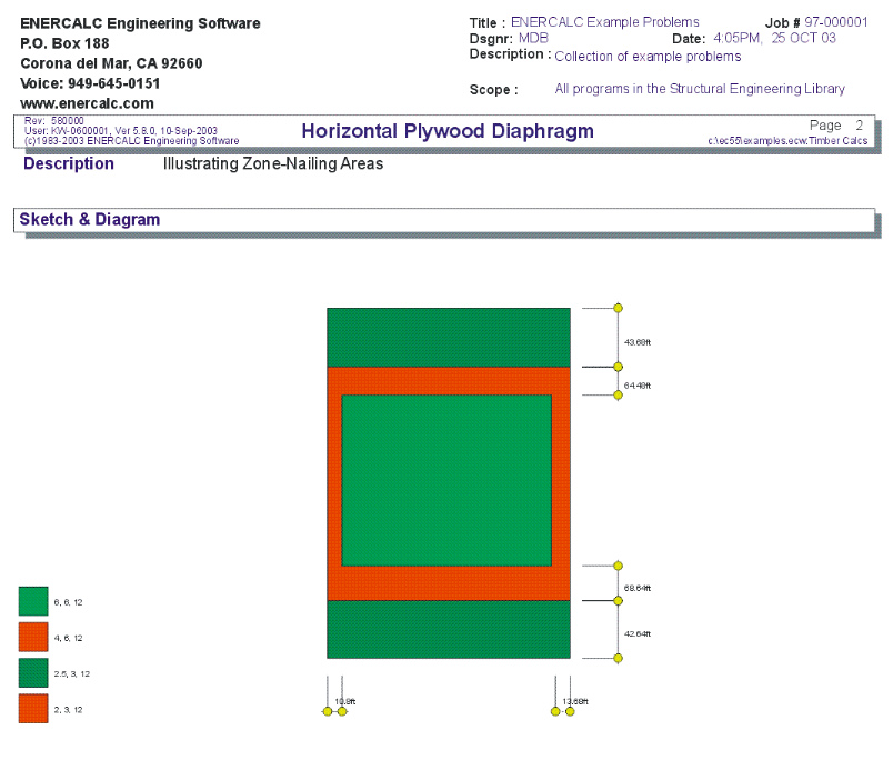
Sketch Tab
This tab provides a sketch of the beam with loads and resulting values shown. Using the [Print Sketch] button will print the sketch in large scale on a single sheet of paper.
The sketch is designed to show the various nailing "zones" in different colors. Within each zone a certain diaphragm design is required according to the framing size, thickness, grade, and nail spacing that are developed in the previous input and "Diaphragm Design" tab.
Sample Printout