|
Multi-Span Steel Beam |

|

|

|

|

|
|
|
Multi-Span Steel Beam |
|
|
|
|

|
Multi-Span Steel Beam
|
Multi-Span Steel Beam |
|
|
|
|
|
|
|
Multi-Span Steel Beam |
|
|
|
|
|
This program provides design and analysis of simple span or continuous steel beams. It allows you to design steel beams in production line form, letting you rapidly complete many designs simultaneously, and can handle up to eight spans at once.
The end fixities of each can easily be modified to model many types of beams, including (but not limited to):
| • | Simple span beams with cantilevers at one or both ends. |
| • | Single span beams with fixed and/or free ends. |
| • | Continuous beams with up to nine supports. |
| • | Continuous beams with one or both ends fixed or cantilevered. |
This flexibility is provided by allowing you to:
| • | Set a flag telling the program to consider all beams that have pinned ends to be either continuous over the support (attached to the adjacent beam) or consider each span is simply supported. |
| • | For each beam, you can specify fixed, pinned, or free support conditions for each end. This allows you to model any type of span support condition you will encounter (limited to eight spans/nine supports). |
Each span can be loaded with a uniform dead and live load, a partial length uniform dead and live load, a partial length trapezoidal dead and live load, up to four point dead and live loads, and one concentrated dead and live moment. To further aid your designing ability, you can easily omit the inclusion of live load on any span to perform alternate span load analysis. For each span, the program determines maximum center and support moments, shears, reactions, and deflections.
Basic Usage
| • | Review Scope of Design/Analysis Task. It is essential that you fully understand the use of this program, since its flexibility is the key to your rapid design of dozens of steel members. Remember that each worksheet column represents a single span between two supports, regardless of the end support conditions. When cantilevers are used, they are considered a span, even though one end is free. |
| • | Spans, Supports, and Allowable Stresses. After you have reviewed the beams you wish to design (and how they will be entered using the programs All Spans Continuous feature and end fixity flags), enter this information in the top section of the worksheet. Remember, when you recalculate the worksheet later to get the results, you can always revise the support fixity data to change any mistakes you might have made. |
| • | LL Flag, Unbraced Lengths, and Load Duration Factor. Use the Live Load Flag to signal whether the live loads you will enter should be applied to the span. You can make changes to these flags to model different live load conditions. Unbraced length specifies the distance between lateral supports of the compression edge. Load duration factor will allow allowable stress increases. |
| • | Distributed Loads. You can apply up to three distributed loads to each span, although the input for each is somewhat different. The first item applies the dead and live load entered to the full span. The second item applies a uniform magnitude dead and live load over all or a portion of the span. The third item allows you to specify a full trapezoidal load to any portion of the span. |
| • | Point Loads & Moments. Point and moment dead and live loads can be applied anywhere on each span. Loads with negative X-distances, or distances that are longer than the span are ignored. |
| • | Modify beam sizes. To refine your design, either type in a new section name and recall the data from the database (see next) and review the stresses and deflections. |
Unique Features
| • | This program has the unique ability to easily analyze and design beams with a variety of span and support conditions. |
| • | Full AISC code checks are made considering length effects on allowable bending stresses. |
| • | A simple flag can be set on any span to ignore all live loads on that span, making alternate span loading analysis easy. |
| • | Very flexible loadings may be applied to each span, including three uniform/partial/trapezoidal loads. |
| • | The program can perform automatic member selection using stress and deflection criteria. All that is required of you is to specify the allowable stresses and desired beam widths. |
Steel Section Database
Built into the software is a complete database of common rolled sections available from various mills in the United States. On each tab labeled #1, #2, etc. there will be a button that looks like this:
![]()
This button displays the steel section database as shown below.
On this window there are various controls and options.....
Steel Database : Allows you to select between several common shapes databases.
Section Type to Display: Allows you to select which steel section designation to display in the list. These shapes conform to the American Institute of Steel Construction shape designations. To make your selection simply move the mouse over the letter(s) and when the highlight activates left-click once with your left mouse button.
Depth Range: This item allows you to specify depth limits to be used for selecting which sections to display in the list. When the checkbox to the left is not checked the selection wording and entries will not appear and all sections will be displayed. These dimensions are compared to the "Depth" dimension of the sections.
Class Range : This item allows you to specify the limits in "Depth Class" to be displayed in the table. The "Depth Class" of a section is the first numeric number in the sections name. For instance a wide flange W14x22 is in depth class "14". a channel C9x15 is in depth class "9", and a L 5x3x1/4 is in depth class "5".
Equal & Unequal Legs : These two buttons appear when you have selected section type "L" which are single angles. The limit the display of the list to angle with equal dimension or unequally dimensioned sides.
Equal Legs, Long Leg Vertical, Short Leg Vertical: These three buttons appear when you have chosen to display section type "LL". These control the display of sections between pairs of angles with both sides of equal length, of unequal side length angles paired with the LONG side together, and unequal side length angles paired with the SHORTside together.
Square & Rectangular Tubes: These two buttons appear when you have chosen section types TS or HSS-T. These are square tubular sections. You can choose to display only square tubes or alternately tubes with unequal sides.
Sort Tabs for Database Table : Immediate above the database list of sections you will see tabs looking like this....
When selected each tab will sort the list in the order described by the text on that tab.
Sort order : These two buttons allow you to chose the list order of the sections. The sorting order will be according to the sort tab selected and shall be in ascending or descending order.
Database Table Itself : The main area on the window will be where the steel sections are displayed as a result of all of your choices as described above.
[Select] : This button is displayed when you have clicked on the [Section] button when you press [Select] the section in the list that is currently highlighted will be selected and the name and data brought into your calculation.
[Insert]: Use this button to add a steel section to the database. When pressed you will see the following window:
The only really important item to enter is the "Type" item. This specifies what standard rolled section type your section is. This item is used internally by the program to decide which stress analysis method to use for determining the sections allowable stress, how to consider unstiffenned elements, and many other code checking items.
[Change]: Will display the same window as above but allow you to change section properties.
[Delete] : Will enable you to delete sections. Note: No sections in the supplied database can be deleted. Only Sections that you ad can be later deleted.
[Cancel]: Exit the steel database window.
ASD & LRFD Design Modes
Allowable Stress Design and Load & Resistance Factor Design as specified by the American Institute of Steel Construction is provided by this program. Only screen captures and descriptions for ASD are presented in this book. More detailed LRFD documentation will be added and will be available in the electronically delivered versions of this book. Check these locations for electronic media:
| • | Latest Adobe Acrobat PDF documentation file here: ftp://208.36.30.226/sel5.pdf. |
| • | Latest Windows Help system file here : ftp://208.36.30.226/enercalc.hlp. |
| • | Internet HTML help documentation presented as web pages at www.enercalc.com/sel_help. |
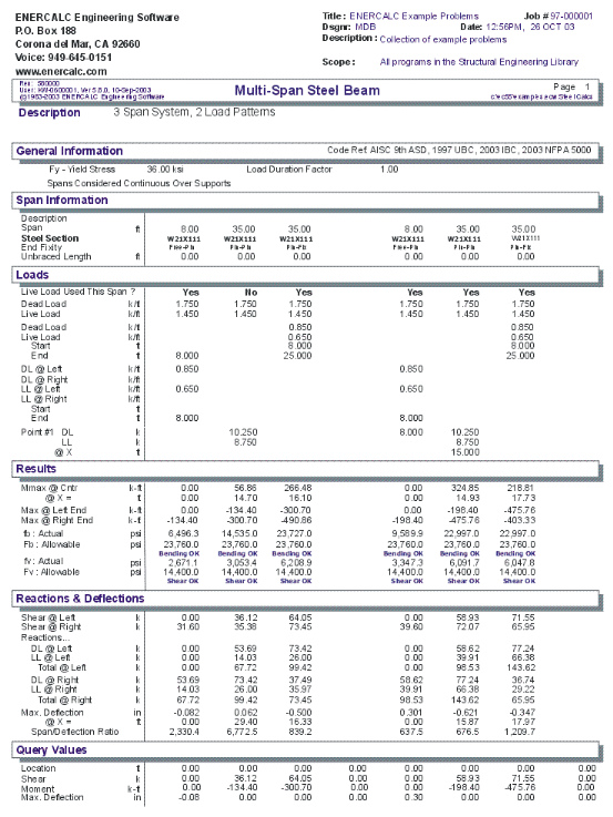
Example
The data entry for this example is shown in the screen captures that accompany the Data Entry Tabs and Results & Graphics Tabs sections to follow.
Data Entry Tabs
This set of tabs provides entries for all input in this calculation. While you are entering data and switching between these tabs you can view the desired resulting information on the tabs on the right-hand side of the screen (calculated values, sketches, diagrams, etc.). A recalculation is performed after any entry data is changed. After each data entry you can view the results on the right-hand set of tabs.
General Tab
Operating Mode
This item plays a critical role in governing the calculation procedure for the entire program.
| • | Spans Considered Continuous Over Support : When two beams share the same support , and the support fixity for both beams at that support is Pinned, then the two beams are tied together to form one continuous beam over that support. |
| • | All Spans Considered as Individual Beams : When two beams share the same support , they are always considered as two separate beams and the stresses and rotations in one never affect the other. |
Within each beam span information tab there is a setting for end fixity. Here is how those end fixities are described according to the selection for this item:
When "All Spans Considered as Individual Beams" is chosen:
| • | Free will indicate that the end is completely free of the support and adjacent beam. |
| • | Pinned will affect the beam according to the end fixity of the adjacent beam. If the adjacent beam end is Fixed or Free, then the beam will be pinned and not affected by the adjacent beam. If the adjacent beam is pinned, the two beams are locked together, forming one beam continuous over the support. |
| • | Fixed will attach the beam end to a rigid boundary element, allowing no rotation or vertical movement, and not linked to the adjacent beam. |
When "Spans Considered Continuous Over Support" is chosen :
| • | Free will indicate that the end is completely free of the support, allowing translation and rotation. |
| • | Pinned will allow the beam end to rotate but not translate. |
| • | Fixed will attach the beam end to a rigid boundary element, allowing no rotation or vertical movement. |
Fy
Steel yield stress used to determine allowable F'b and Fv.
Typical Span Tab : #1 to #8
Each tab that shows #1 through #8 specifies information for one of the beams of the multi-span beam. Tab #1 is the left-most beam and you work to the right to define additional adjacent spans.
Span Description
Enter a brief description of this span. Leaving it blank is fine.
Span
This equals the span distance of a beam segment.
Unbraced Length
If the span will have the compression edge laterally unbraced for some distance, enter the distance here. This length will be used to determine whether the beam falls into the short, intermediate, or long beam classification for determination of allowable bending stress.
For continuous beams, remember that the true meaning of this value is distance between points of contra flexure, and most likely will NOT be the distance between supports.
Left Fixity, Right Fixity
Specifies how the ends of the beam will be restrained.
Steel Section
This is where you specify the rolled steel section to be used in the design. There are two ways to enter & specify the section.
| • | Use the [Section] button to retrieve the section from the built-in steel database. See the description given previously for more information. |
| • | Type in the section name and the program will automatically look through the database for a match. Upper or lower case is fine. If found the name and numeric section properties will be retrieved into this calculation. The numeric properties will be seen on the "Section Properties" tab. |
Apply Live Load This Span?
This entry controls whether or not the live load entered for the span will be used or ignored. A YES/NO entry here gives you a simple way to try various live load alternates to determine maximum moments and shears on multi-span beams.
Applied Loads Tab
Uniform
Uniform dead and live load applied to the entire length of the center span. You should be aware that beam weight is not considered in the program, therefore this input should include allowance for beam weight. These values may be positive or negative.
Partial Length Distributed
Uniform dead and live load applied over a full or partial length of the center span. X-Left indicates the distance from the left support to the beginning of the load, and X-Right is the distance from the left support to the right end of the load. These values may be positive or negative.
Trapezoidal Distributed
Uniform or varying dead and live load applied over a full or partial length of the center span. DL/LL @ Left indicates the dead or live load magnitude at the X-Left distance location. DL/LL @ Right indicates the dead or live load magnitude at the X-Right distance location. These values may be positive, negative, or both. X-Left indicates the distance from the left support to the beginning of the load, and X-Right is the distance from the left support to the right end of the load.
Point Load
Concentrated dead and live load applied to the beam.
Moment
Dead and live moment applied to the beam.
Section Properties Tab
This secondary tab is where the steel section properties are listed. The properties shown here are used for the calculation.
The typical steel section measurements are given for the section chosen. When certain sections are used, the measurements will not conform to the typical W section naming conventions used here:
| • | For Tubes , Flange Thickness and Wall Thickness will both be set equal to the tube's wall thickness. rT is not used. |
| • | For Pipe , Flange Thickness and Wall Thickness both equal the pipe's wall thickness. Flange Width and Depth will both be set to the pipe's outside diameter. rT is not used. |
| • | For Channels , rT equals the distance from the flat face to the center of gravity of the section. |
| • | For Tees , rT equals the distance from the top of the flange to the center of gravity of the section. |
| • | For Double Angles , rT equals the spacing between the backs of the angles. |
| • | For Single Angles , rT is not used. |
Results & Graphics Tabs
This set of tabs provides the calculated values resulting from your input on the "Data Entry Tabs". Because a recalculation is performed with each data entry, the information on these tabs always reflects the accurate and current results, problem sketch, or stress/deflection diagram.
Results Tab
Moments
These are the maximum values to use for design for this span. The "Mid-Span" moment can occur anywhere between the two end supports. It is possible that this number is right next to the support.
To determine maximum moments, the following technique is used:
| • | Fixed end moments are calculated for each span. When LL Flag is set to NO, no live loads are applied to that span. |
| • | A 16 pass moment distribution is performed on the entire eight span system. |
| • | The resulting end moments are then applied to each beam end and the resulting moments, shears, and deflections for the span are calculated. Each beam is divided into 250 increments for this process. |
Bending Stress
Allowable bending stress calculated considering Cf, load duration factor, and from the evaluation of allowable bending stress, due to the unbraced length. Actual bending stress is the maximum of positive or negative moment, divided by section modulus of the beam at that span location. Continuous beams will have this value equal to the maximum stress between the supports.
Shear Stress
Allowable stress is calculated load duration factor applied to Fv (see below). Actual shear stress is the maximum unit shear stress at the end of the beam. To determine net shear at the beam end, all loads within a distance d away from the end of the member are subtracted from the end shear. This value is multiplied by 1.5 and divided by beam width times beam depth. When the beam is continuous over a support, shear on BOTH SIDES of the support is evaluated.
Maximum Deflection
Using the applied loads, support fixities, and moment distribution results, the resulting deflection curve at 250 points along the beam is searched for the maximum deflection and location. This is the maximum deflection, considering both upward and downward displacements. Negative sign is downward deflection.
Shear @ Support
The calculates shears at each support are given. This value is the maximum shear after checking both sides of the support.
Reactions
Reactions are calculated using dead load and the live load as selected to be applied for each span.
Query Values
In this area you can enter a distance location along the span, measured from the left support, ad have the shear, moment, and deflection at that location calculated.
Sketch Tab
This tab provides a sketch of the beam with loads and resulting values shown. Using the [Print Sketch] button will print the sketch in large scale on a single sheet of paper.
Diagrams Tab
This displays a moment, shear, and deflection diagram for the beam with the applied loads and end conditions. Note the two tabs...."Graphic Diagram" and "Data Table". The Data Table tab provides the entire internal analysis at the 1/500th points within the beam.
!
Printing Tab
This tab allows you to control which areas of the calculation to print. Checking a box will signal that the information described by the item will be printed. However, if there is no information in for a particular selection it will not be printed. So these checkboxes are best described as "If this particular area of the calculations contains data then print it".
Sample Printout