|
Bolt Group in Timber Member |

|

|

|

|

|
|
|
Bolt Group in Timber Member |
|
|
|
|

|
Bolt Group in Timber Member
|
Bolt Group in Timber Member |
|
|
|
|
|
|
|
Bolt Group in Timber Member |
|
|
|
|
|
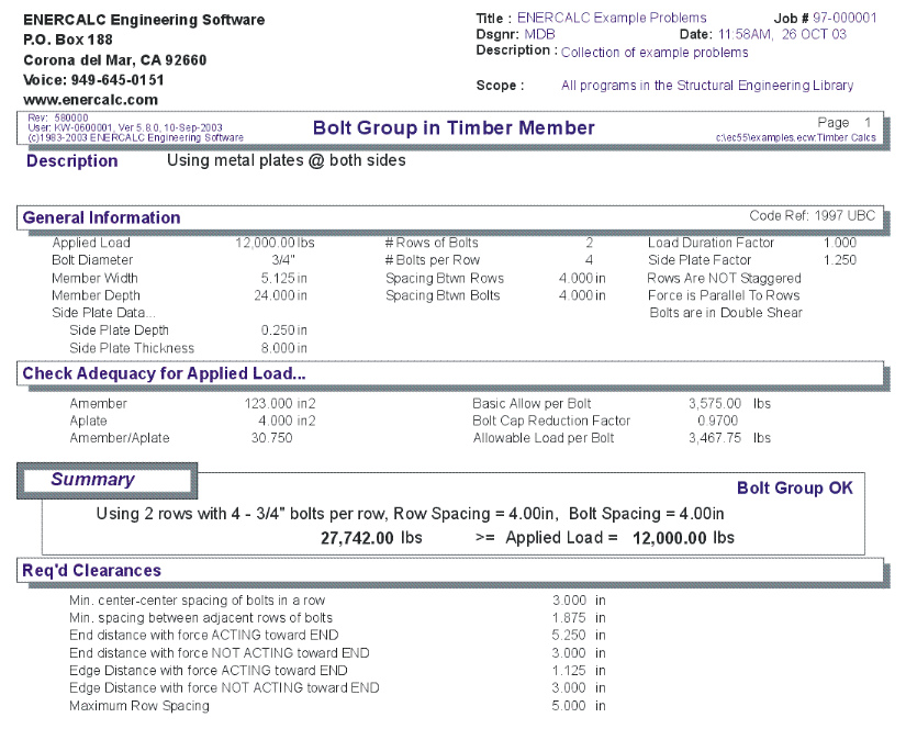
This program analyzes bolts in wood members subjected to forces either parallel or perpendicular to the center of gravity of the bolt group. It considers single or double shear, wood or metal side plates, load duration and side plate stress increase factors, and the reduction effect on bolt groups when forces are parallel to a rows of bolts.
The program performs two functions. When the number of bolts is unknown for a given load and member size, the program can determine the number of bolts required in each row considering the bolts-in-a-row capacity reduction effects.
When the bolt group configuration is known, an analysis of the bolt group combines all input and determines the allowable bolt group load.
Special features allow the user to use either wood or steel side plates on one or both sides, and have all the associated effects considered. The program also provides a listing of the minimum required edge distances, end distances, bolt spacing, and row spacing which are applicable to your input. You can then cross check your values to ensure everything is within limits.
Basic Usage
To Determine # Of Bolts Required: Enter all data except the number of bolts per row. You can estimate almost all of the sizes, because the program's first bolt quantity can be used as a starting point for refinement of nearly all other values. You can refine all the input data except the number of bolts, then enter the number of bolts per row and refine the other data items. When you enter a number in the Number of Bolts In A Row cell, the bolt analysis section will show the results of the complete analysis of the bolt group.
To Analyze A Bolt Group: Enter all the design values and calculate. The bolt group capacity will be shown for your use.
Assumptions & Limitations
| • | All loads must be applied along one axis and act through the center of stiffness of the bolt group. No provisions are made in the program for eccentric loadings. |
Example
The data entry for this example is shown in the screen captures that accompany the Data Entry Tabs and Results & Graphics Tabs sections to follow.
Data Entry Tabs
This set of tabs provides entries for all input in this calculation. While you are entering data and switching between these tabs you can view the desired resulting information on the tabs on the right-hand side of the screen (calculated values, sketches, diagrams, etc.). A recalculation is performed after any entry data is changed. After each data entry you can view the results on the right-hand set of tabs.
General Tab
Applied Load
Enter the applied load here
Load Direction
Enter the direction of the applied loading with respect to the grain of the members. This item is used to determine the allowable basic capacity of the bolts specified.
Bolt Diameter
Enter the bolt diameter to be used in the design or analysis. The diameter should be entered in decimal form, and should coincide with a bolt listed in UBC.
# Of Rows Of Bolts
Indicates the number of rows of bolts to be used. This item should always be entered, whether or not your are performing a design or analysis.
# Of Bolts In A Row
An entry here may or may not be made. If no entry is made, the program will use all other values, along with Applied Load Parallel To Rows to determine a minimum number of bolts per row which will be needed. If an entry is made here, it will be used in the Bolt Group Analysis to determine the capacity of the bolt group.
Staggered?
If the bolt group is staggered, enter 1 to indicate this.
Spacing Between Rows
When two or more rows of bolts are used, this is the spacing between those rows.
Spacing Between
Bolts his is the spacing between each bolt in a row, and will effect the calculations when bolts are staggered and spaced very close.
Shear Type : Single or Double
Specify whether the bolts are in single or double shear. Single shear will typically mean that two members are being attached, while Double would mean that three are used, such as a wood member being bolted between two steel plates.
Member Width & Depth
Enter the width and depth of the main wood member for which the bolt capacities should be retrieved.
Load Duration Factor
If the load applied to the bolt group is of short term nature, enter the desired factor which will increase the bolt capacity. Typically a value of 1.33 is used.
Side Plate Factor
If metal side plates are used, the user may desire to enter a load factor which will increase the bolt capacity. Typically a value of 1.25 is used.
Side Plate Data
Width is measured parallel to the depth of the member, and thickness is measured parallel to the width of the member. The program will automatically double the side plate area when Double Shear has been specified.
Results & Graphics Tabs
This set of tabs provides the calculated values resulting from your input on the "Data Entry Tabs". Because a recalculation is performed with each data entry, the information on these tabs always reflects the accurate and current results, problem sketch, or stress/deflection diagram.
Results Tab
Applied Load & Capacity
These are the results of the analysis giving applied and allowable values.
Code Allowable Bolt Capacity
This indicates the basic allowable load per bolt, considering direction of load to grain, diameter, and width of main member. If there is no available bolt value from the table, 0" will be displayed.
Amember, Aplate, Ratio
These values are used to calculates a reduction factor based on the ratio of member area to the side plate area.
Basic Allowable Per Bolt
This value is the result of multiplying the basic bolt capacity by the Load Duration Factor and Side Plate Factor.
Bolt Capacity Reduction Factor
The reduction factor also considers the number of bolts in a row. This factor is applied to the Basic Allowable Per Bolt (see next) to determine the actual allowable bolt value considering the group's effect. The factors can be found in the Design Handbook published by the American Institute of Timber Construction.
Allowable Load per Bolt
This is the Basic Allowable per bolt times the "Bolt Capacity Reduction Factor".
Two Parallel Rows being used as one row ?
This Yes/No item reports whether the program is considering two adjacent rows as one row because of limitations on bolt row spacing and spacing between bolts.
Req'd Bolt Clearances
Based on code requirements, the minimum spacings and edge & end distances are given here.
Sketch Tab
This tab provides a sketch of the beam with loads and resulting values shown. Using the [Print Sketch] button will print the sketch in large scale on a single sheet of paper.
Sample Printout