|
Timber Column |

|

|

|

|

|
|
|
Timber Column |
|
|
|
|

|
Timber Column
|
Timber Column |
|
|
|
|
|
|
|
Timber Column |
|
|
|
|
|
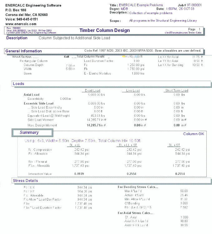
This program analyzes timber columns subjected to a combination of axial load (with optional eccentricities), side bracket load, and applied transverse moment. Either rectangular or round columns may be analyzed.
In order to properly consider the effects of column slenderness and unbraced compression edge effects, the user enters the unbraced lengths for each axis of axial instability, and enters a separate unbraced length for determining the allowable bending stress about the X axis.
Basic Usage
| • | Column Dimensions & Lengths. Use the Depth, Width, and Actual/Nominal entries for rectangular columns, or Column Diameter for circular columns (which is always considered the actual diameter). The X-X and Y-Y axial unbraced lengths are used to determine allowable axial stress considering buckling effects. X-X Bending unbraced length is used to determine allowable bending stress considering length effects. |
| • | Allowable Stresses. Enter the allowable basic compressive stress for the column Parallel to Grain, and allowable bending stress about the X-X (width) axis. These basic allowable stresses will be modified by the Load Duration Factor, size factor, axial slenderness, and bending slenderness to give the net allowable stress values. |
| • | Applied Loads. Axial Load can be applied at an optional eccentricity to the column centerline (creating an X-X moment at the top of the column). Transverse moment will be considered a maximum moment midspan between the ends. Side load is applied at a Dist. from CL, creating a concentrated moment between the ends. All column loads are combined and the incremental points along the column evaluated for combined axial and bending to give the final results. |
Unique Features
Axial load & eccentricity, side bracket load, and applied transverse moment may be applied to the column for analysis
| • | Either a rectangular or round column may be analyzed. |
| • | Complete AITC interaction equations are evaluated. |
Example
The data entry for this example is shown in the screen captures that accompany the Data Entry Tabs and Results & Graphics Tabs sections to follow.
Data Entry Tabs
This set of tabs provides entries for all input in this calculation. While you are entering data and switching between these tabs you can view the desired resulting information on the tabs on the right-hand side of the screen (calculated values, sketches, diagrams, etc.). A recalculation is performed after any entry data is changed. After each data entry you can view the results on the right-hand set of tabs.
General Tab
Total Column Height
When you wish to analyze a circular column, the diameter is entered here. Please note that any entry in this location (except zero) will overwrite the depth/width dimensions, and the analysis will continue for the circular column.
Le XX for Axial
Unbraced length used to calculate compression slenderness. This is the distance between elements that support the column from failing by deflecting along the "X-X" axis which is along the column's "width" dimension.
Le YY for Axial
Unbraced length used to calculate compression slenderness. This is the distance between elements that support the column from failing by deflecting along the "Y-Y" axis which is along the column's "width" dimension.
Lu XX for Bending (Unbraced Length)
This entry specifies the unbraced length to be used for calculating allowable bending stress in the column. This is the distance between lateral supports that brace the beam from failure due to movement of the compression edge along the column's "X-X" axis (which is the width direction), and are the k*Lu values used to determine column slenderness.
[Wood Section] button and entry
Use this button to display the database of wood sections. The database provides selections for sawn, glued-laminated, and manufactured lumber. Please refer to the previous chapter describing using database in the Structural Engineering Library. Pressing [Wood Section] will display the following selection window:
Depth & Width
Enter the beam width & depth you wish to use, or select the beam from the database (see above).
Column Type
This selection controls how the Size of Volume factor is calculated. If "Sawn" is selection "Cf" is calculated. If "GluLam" is selected then "Cv" is calculated. If "Manufactured or So. Pine" selected then NO factor (Cf or Cv) is calculated.
Wood Species : [Stress] button & entry
This allows you to use the built-in NDS & Manufactured lumber allowable stress database to retrieve allowable stresses. When you press the button you will see this selection window. Please see the section earlier in this User's Manual that give information and usage for the databases.
Fc:Parallel
Allowable compressive stress parallel to the grain, when length effects do not apply.
Fb:Bending
Allowable bending stress in the column when bracing effects do not apply (Le = 0).
E : Elastic Modulus
Elastic modulus of wood column used.
Load Duration Factor
Short term stress increase factor to be applied to allowable stresses.
Loads Tab
Axial Load
This defines the axial load applied to the top of the column. It can be applied, optionally, at the eccentricity defined below.
Eccentricity
Eccentricity of the axial load defined above. This eccentricity is in reference to the X-axis only, and may be entered as positive or negative.
Applied Transverse Moment
This is a user-defined moment applied to the column between supports. This represents a magnitude only, and is added to the other moments calculated.
Eccentric Side Load
Enter the vertical load applied eccentrically to the column between top and bottom ends. Based upon the distance and height entries to follow, this load is transformed into an equivalent lateral point load on the column to determine the moment it induces.
Side Load Eccentricity (Distance from column Centerline)
This defines the distance from column centerline to the point of side load application.
For axial load, positive ecc. = positive moment.
For side load, positive ecc. = positive moment
All positive moments will be added to obtain Max. Design Moment .
Equivalent Load @Mid-height
This load is determined from the following formula :
P' = Ecc. * L' * P / L 2 L = Total column height
Applied laterally at mid-height of the column to determine the moment induced from the side bracket load. This moment = P' * L / 4.
Side Load Moment This moment = P'L/4
Maximum Design Moment
From the previously entered loads, moments and eccentricities, a final maximum moment is determined to be used for analysis.
Results & Graphics Tabs
This set of tabs provides the calculated values resulting from your input on the "Data Entry Tabs". Because a recalculation is performed with each data entry, the information on these tabs always reflects the accurate and current results, problem sketch, or stress/deflection diagram.
Results Tab
fc : Compression
Equals the total axial and side load divided by the column area. Remember, when Nominal is chosen, the true net column dimensions are used.
Fc : Allow Axial Compression Stress
The allowable axial stress as defined in the items to follow, multiplied by the load duration factor.
fbx : Actual Flexural
Equals the Maximum Design Moment divided by the actual section modulus of the column specified.
This equals the total bending moment divided by the column's X-X section modulus.
F'bx : Allowable Bending
The allowable bending stress as defined in the items to follow, multiplied by the load duration factor.
Interaction Value
This is the typical interaction equation used for timber column design. It is defined in the NDS code, and other codes and references. This is the final calculation of all values in the interaction equation to determine the final state of combined stresses.
For Bending Stress Calculations
Max k Lu/d
Allowable k Lu/d For Rectangular Columns = 50
For Circular Columns = 43.
"K" represents the minimum value of Lu/d at which the column can be expected to perform as a Euler column. This is taken as :
| • | Rectangular Columns: 0.671 * [ E / (FC * LDF ) ]½ |
| • | Circular Columns: 0.582 * [ E / (FC * LDF ) ]½ |
k Lu/d
This equals : Le / Column Depth
Min. Allow K Lu/d
This represents the value of k Lu / d at which the effects of slenderness must be considered. This is :
| • | Rectangular Columns: 11 |
| • | Circular Columns: 9 |
C-f : Bending
Defines the stress reduction factor to be applied when the column depth exceeds 12" and bending stresses are present.
Rb : (Le d / b^2 ) ^ .5
This is the slenderness factor based upon the defined effective length "Le". It is used to determine the adjusted allowable bending stress based upon column slenderness under beam action (Compression face stability)
For Axial Stress Calculations
Axial ( Le-xx * k * / Column Depth)
This is the actual slenderness of the column that will be used to calculate allowable Fa values when the column is checked about out-of-plane buckling movement about the columns X-X axis (which is parallel to the width of the section)
Axial ( Le-yy * k * / Column Width)
This is the actual slenderness of the column that will be used to calculate allowable Fa values when the column is checked about out-of-plane buckling movement about the columns X-X axis (which is parallel to the width of the section)
Sketch Tab
This tab provides a sketch of the beam with loads and resulting values shown. Using the [Print Sketch] button will print the sketch in large scale on a single sheet of paper.
Notes Tab
This tab contains some general notes about the usage of the results of this program.
Printing Tab
This tab allows you to control which areas of the calculation to print. Checking a box will signal that the information described by the item will be printed. However, if there is no information in for a particular selection it will not be printed. So these checkboxes are best described as "If this particular area of the calculations contains data then print it".
Sample Printout