|
Timber Beam & Joist Design |

|

|

|

|

|
|
|
Timber Beam & Joist Design |
|
|
|
|

|
Timber Beam & Joist Design
|
Timber Beam & Joist Design |
|
|
|
|
|
|
|
Timber Beam & Joist Design |
|
|
|
|
|
This program provides design and analysis of up to seven simple beams on one calculation page. We've designed it primarily for rapid design of joists, rafters, and headers, and other wood members with simple loadings.
As you view the worksheet, you will notice seven side-by-side columns, each of which represents a single beam. In each of those columns, you can enter beam size data, allowable stresses, span lengths, and loads and view calculated output consists of stresses, reactions, shears, and deflections, and span/deflection ratios.
The program automatically applies live loads to the center span, cantilever span, and the entire span when calculating maximum moments, shears, reactions and deflections. This eliminates the need for you to change loadings to find all the maximum conditions.
Unique Features
| • | The user has the ability to quickly design up to seven beams or joists in this one program. |
| • | Live loads are automatically skip-loaded when cantilevers are present to get maximum moments, shears, reactions, and deflections. |
| • | The program checks depth factor and unsupported lengths to calculate allowable bending stresses. |
| • | The actual shear stress is calculated at a distance d from each support. |
Assumptions & Limitations
| • | You must enter the actual beam depth and width. |
| • | Beam ends can't be fixed nor can purely cantilever beams be analyzed. For this condition use either the Heavy Timber Beam or Multi-Span Timber Beam programs. |
| • | Beam weight is not automatically added to entered loads. |
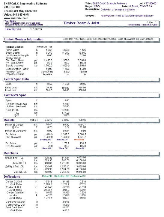
Example
The data entry for this example is shown in the screen captures that accompany the Data Entry Tabs and Results & Graphics Tabs sections to follow.
Data Entry Tabs
This set of tabs provides entries for all input in this calculation. While you are entering data and switching between these tabs you can view the desired resulting information on the tabs on the right-hand side of the screen (calculated values, sketches, diagrams, etc.). A recalculation is performed after any entry data is changed. After each data entry you can view the results on the right-hand set of tabs.
General Tab
This tab contains only the input for a general description. Because this program designs individual beams on each tab all the entry information is contained on that particular tab.
Beam Tabs : #1 through #7
On each of these tabs you can design a complete beam. Each beam is simply span with an optional cantilever.
[Wood Section] button and entry
Use this button to display the database of wood sections. The database provides selections for sawn, glued-laminated, and manufactured lumber. Please refer to the previous chapter describing using database in the Structural Engineering Library. Pressing [Wood Section] will display the following selection window:
Width & Depth
Enter the exact dimensions of the beam section being used. You can quickly change this entry to optimize your design. Also, the automatic member sizing will place a depth here.
Beam Type
This selection controls how the Size of Volume factor is calculated. If "Sawn" is selection "Cf" is calculated. If "GluLam" is selected then "Cv" is calculated. If "Manufactured or So. Pine" selected then NO factor (Cf or Cv) is calculated.
[Stress] button & entry
This allows you to use the built-in NDS & Manufactured lumber allowable stress database to retrieve allowable stresses. When you press the button you will see this selection window. Please see the section earlier in this User's Manual that give information and usage for the databases.
Fb:Basic
Enter the basic code-allowable bending stress here. Do not multiply it by any factors (load duration, depth, and slenderness). The program will calculate all appropriate factors, apply them to this value, and display the final Fb:Allowable value in the RESULTS section.
Fv: Basic
As for Fb:Allow described above, enter the basic code allowable shear stress.
Elastic Modulus
The elastic modulus should be entered in KSI, i.e. 1,700 ksi. This value is used to calculate deflections and allowable stress factors for long slender beams.
Load Duration Factor
This factor will modify the allowable bending and shear stresses. Since this value is applied to allowable values, your STRESS RATIO values should always be less than one.
Center Span TAB
This tab allows you to enter span length, unbraced length, and loads applied to the main span of the wood beam.
Center Span Length
Enter the length of the main beam span.
Le: Unbraced Length
Enter the unbraced length of the compression edge of the beam that is to be used for calculation of allowable bending stress based on possible failure of the beam by lateral-torsional buckling.
Uniform Loads
You can enter dead and live loads applied to the full length of the center span. This load has uniform intensity for the entire beam length.
Partial Load
Loads Here you can enter a uniform intensity dead and live load over all or just part of the beam's center span. X-Left is the starting point of the load with respect to the left support. X-Right is the ending point. Leaving both X-Left and X-Right zero will apply the load to the entire center span.
Point Loads
Up to four dead and live concentrated load can be applied to the center span. X-Dist. is the load's location from the left support.
Cantilever Span TAB
This tab allows you to an optional cantilever along with it's unbraced length and the applied loads.
Cantilever Length
Enter the length of the main beam span.
Le: Unbraced Length
Enter the unbraced length of the compression edge of the beam that is to be used for calculation of allowable bending stress based on possible failure of the beam by lateral-torsional buckling.
Uniform Loads
You can enter dead and live loads applied to the full length of the center span. This load has uniform intensity for the entire beam length.
Span Point Loads
Two dead and live concentrated load can be applied to the center span. X-Dist. is the load's location from the left support.
Results & Graphics Tabs
This set of tabs provides the calculated values resulting from your input on the "Data Entry Tabs". Because a recalculation is performed with each data entry, the information on these tabs always reflects the accurate and current results, problem sketch, or stress/deflection diagram.
Results Tab
M:max @ Center Span
This is the maximum moment within the center span. When a cantilever is present, any live loads are skip loaded to determine maximum moment.
Moment @ Right Support
This is the moment at the right support due only to the full dead and live load being applied to the cantilever.
Stress Ratio
Overall maximum actual / allowable stress ratio for the beam
Bending Stresses
Fb: Allow : Final allowable bending stress after calculating all modifications due to load duration, depth factors, and reductions for long unbraced compression edges.
Fb: Actual : Actual maximum bending stress along the full length of the beam.
Shear Stresses
Fv: Allow : Final allowable shear stress after applying the load duration factor.
Fv: Actual : Actual maximum shear stress at either end of the beam.
Reactions
Dead and live load support reactions. Live load reaction is the maximum reaction resulting from skip-loading when a cantilever is used.
Deflections
These are all the maximum dead and live load deflections and their distance from supports. Live load deflections result from Skip loading when a cantilever is present. The Length/Deflection ratios are multiplied by 2 for cantilevers, to adjust them to equivalent simple span deflection ratios.
Sketch Tab
This tab provides a sketch of the beam with loads and resulting values shown. Using the [Print Sketch] button will print the sketch in large scale on a single sheet of paper.
Diagrams Tab
This displays a moment, shear, and deflection diagram for the beam with the applied loads and end conditions. Note the two tabs...."Graphic Diagram" and "Data Table". The Data Table tab provides the entire internal analysis at the 1/500th points within the beam.
Notes Tab
This tab contains some general notes about the usage of the results of this program.
Printing Tab
This tab allows you to control which areas of the calculation to print. Checking a box will signal that the information described by the item will be printed. However, if there is no information in for a particular selection it will not be printed. So these checkboxes are best described as "If this particular area of the calculations contains data then print it".
Sample Printout