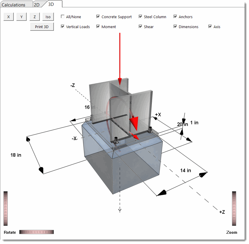
This module designs steel column base plates according to the latest Edition AISC Steel Construction Manual and the AISC Design Guide 1, Second Edition.
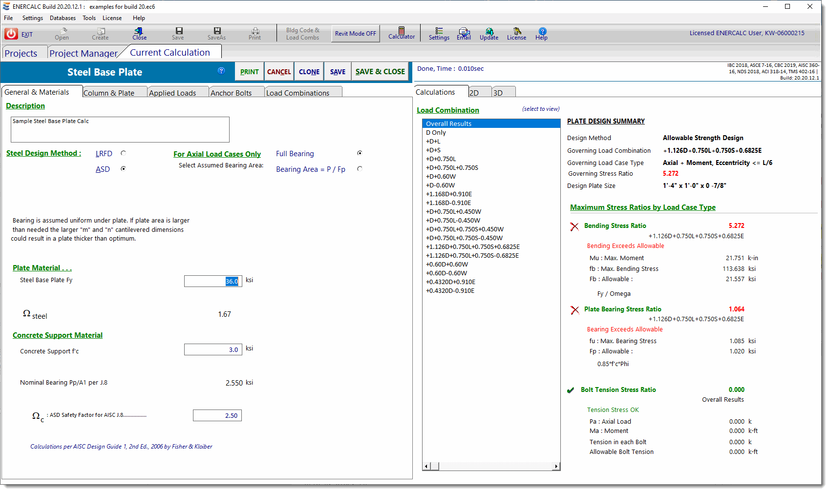
This module handles base plate design for the following conditions:
•where the resultant eccentricity is zero,
•where the resultant eccentricity is within the middle third for full bearing pressure,
•where the resultant eccentricity is outside the middle third resulting in a triangular pressure distribution on part of the base plate, and
•extreme eccentricity conditions where anchor bolts are required.
This module does not handle conditions where NET UPLIFT is present. When the summation of factored axial loads in a load combination is negative, then uplift controls and the module will not calculate. Under these conditions, a red error message will be displayed in the status bar to notify you of this condition. Consider using the Steel Base Plate by FEM module for these situations.
General & Materials
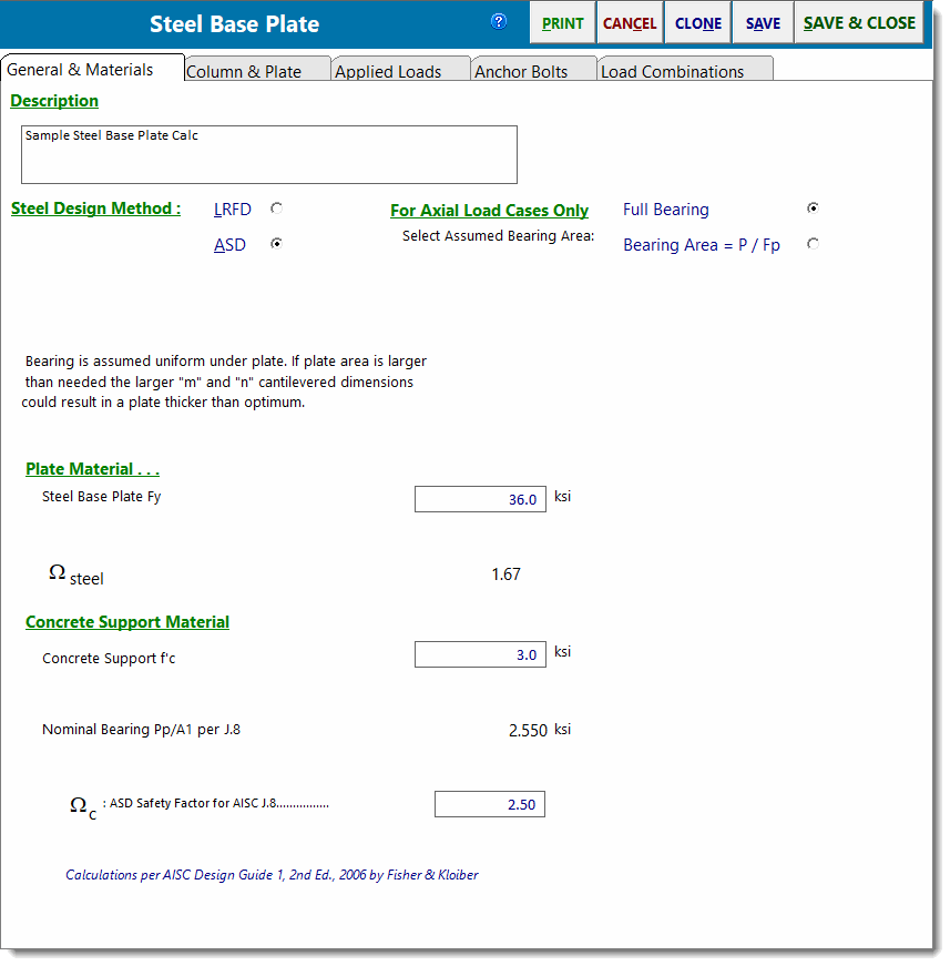
Steel Design Method
Select between ASD or LRFD design methods.
For Axial Load Cases Only....
This selection controls the upward pressure used to design the plate. A brief description of each choice is provided below the buttons for each selection.
Full Bearing: Bearing is assumed uniform under plate. If plate area is larger than needed, the larger "m" and "n" cantilevered dimensions could result in a thicker plate than would be required if the pressure was calculated by the other option.
Bearing Area = P / Fp: Base plate is considered flexible with bearing concentrated close to column. Maximum Fp is used to calculate ''design'' minimum plate size. Determining the bearing pressure by this method might result in thicker plates if bending stress is high between webs or within pipe or tube walls.
Steel Base Plate Fy
Specify the yield strength of the base plate material.
ASD: Omega
Enter the capacity reduction factor, Omega, to be used in ASD per AISC 360.
LRFD: Phi
Enter the capacity reduction factor, Phi, to be used in LRFD per AISC 360.
Concrete Support f'c
28-day compressive strength of concrete used to support the base plate.
ASD: Omega per AISC J.8
AISC 360 Section J.8 specifies Omega as 2.5. This entry allows the value to be modified.
LRFD: Phi per AISC J.8
AISC 360 Section J.8 specifies Phi as 0.6. This entry allows the value to be modified.
Column & Plate
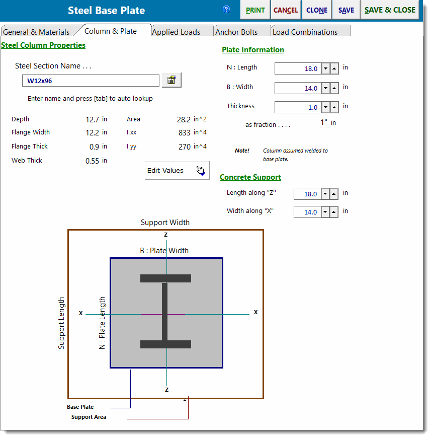
Steel Section Name & Database Button
Type the AISC section name in the entry and press [Tab]. The module will look up the section in the Steel database and, if found, will retrieve the values. The name must be typed just as it appears in the AISC Steel Construction Manual.
Or click the [Section Database] ![]() button to display the built-in steel database and select a section.
button to display the built-in steel database and select a section.
[Edit Values] Button
Clicking this button will allow you to enter the steel properties.
Plate Information
Enter the length, width and thickness of the base plate. Use the ![]() buttons to quickly change the values...the results are instantly recalculated.
buttons to quickly change the values...the results are instantly recalculated.
Concrete Support
Enter the support dimensions that will be used to calculate the allowable bearing pressure increase, A1 * sqrt(A2/A1).
Applied Loads
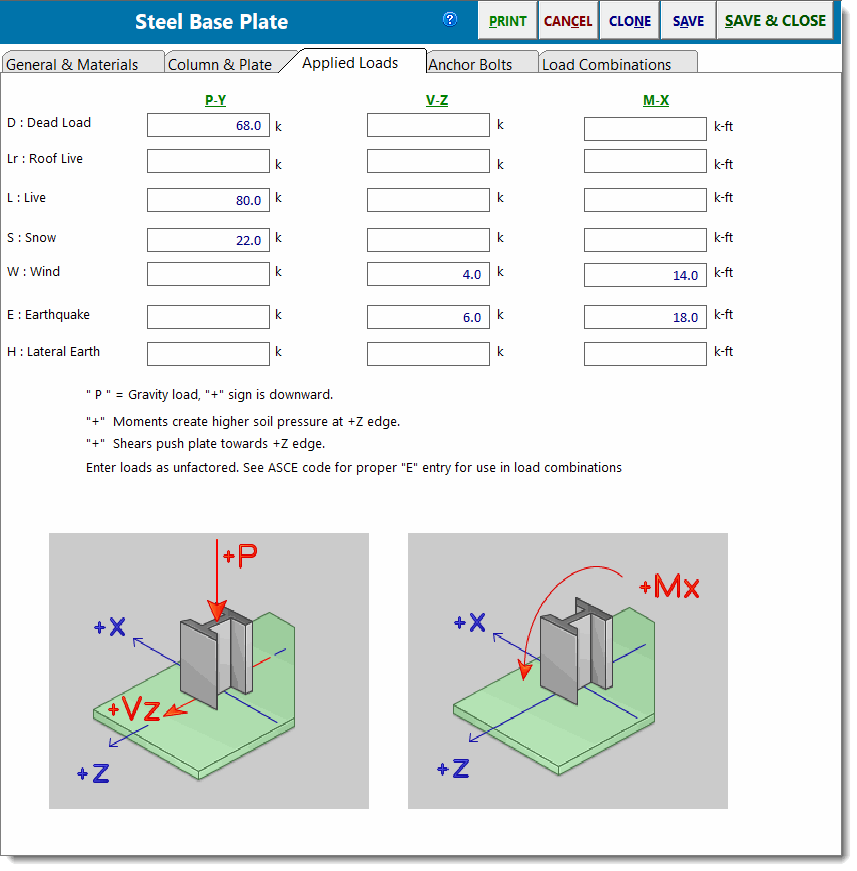
Py - Axial Load
This column of entries specifies the axial load applied to the base plate. Note that positive values represent downward loads.
Vz - Shear
This column of entries specifies the shear applied parallel to the plate and to be resisted by the anchor bolts.
Mx - Moment
This column of entries specifies the moment that the column applies to the plate.
Anchor Bolts
Items on this tab specify the strength and location of the anchor bolts that will resist shear and tension.
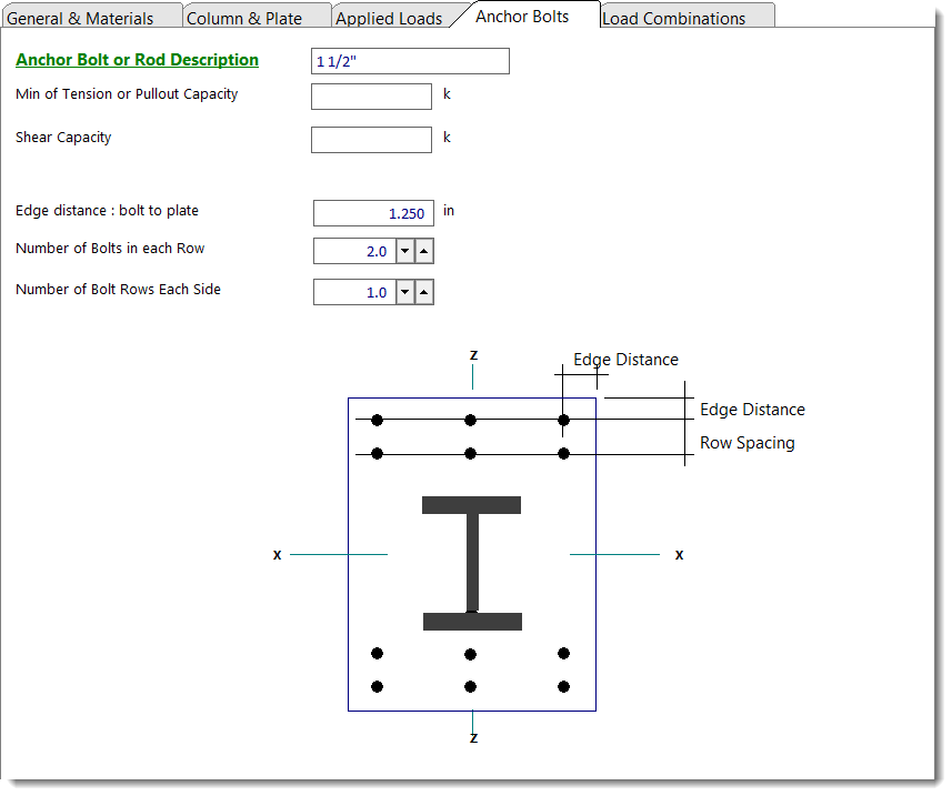
Description
Text description of the bolt for your reference. Not used by module.
Tension Capacity
Net tension capacity of bolt after all capacity factors are applied.
Shear Capacity
Net shear capacity of bolt after all capacity factors are applied.
Edge Distance
Distance from edge of plate to center of bolt closest to edge.
Number of Bolts in a Row
The "Row" referred to is a row of bolts at the plate edge that will take any tension force.
Number of Bolt Rows
Number of rows of bolts on each side.
Row Spacing
Spacing of rows when more than one row is used.
Load Combinations
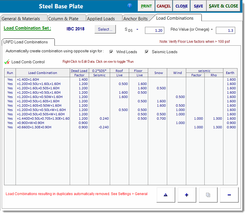
This tab displays the load combinations used for either the ASD or LRFD method.
The screen capture below shows a sample of the load combinations factors:
Calculations - Overall
The Calculations tab contains a list of load combinations on the left and a summary of all the calculated values for each load combination on the right. Click one of the load combinations in the list to view results specifically for that load combination.
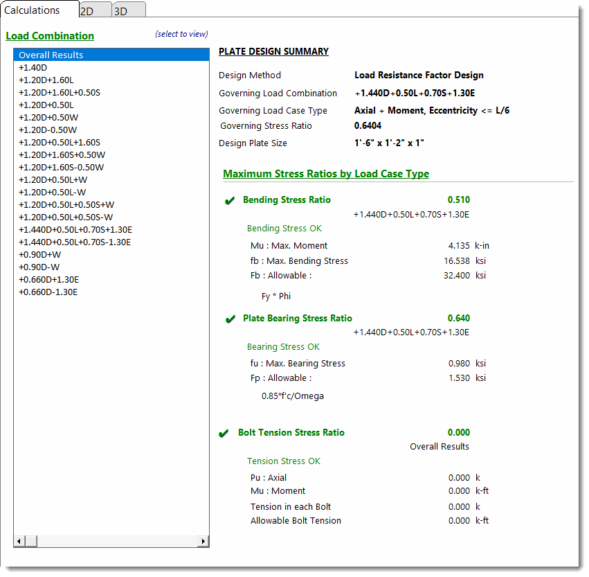
The very first item in the list will always say Overall Results. The module will examine the results for all of the load combinations and determine which gives the extreme condition of stress and presents it the Overall Results item. This is the governing case for the base plate.
Note that Maximum Bending Stress is calculated using the plastic section modulus, in keeping with AISC Design Guide 1, Second Edition.
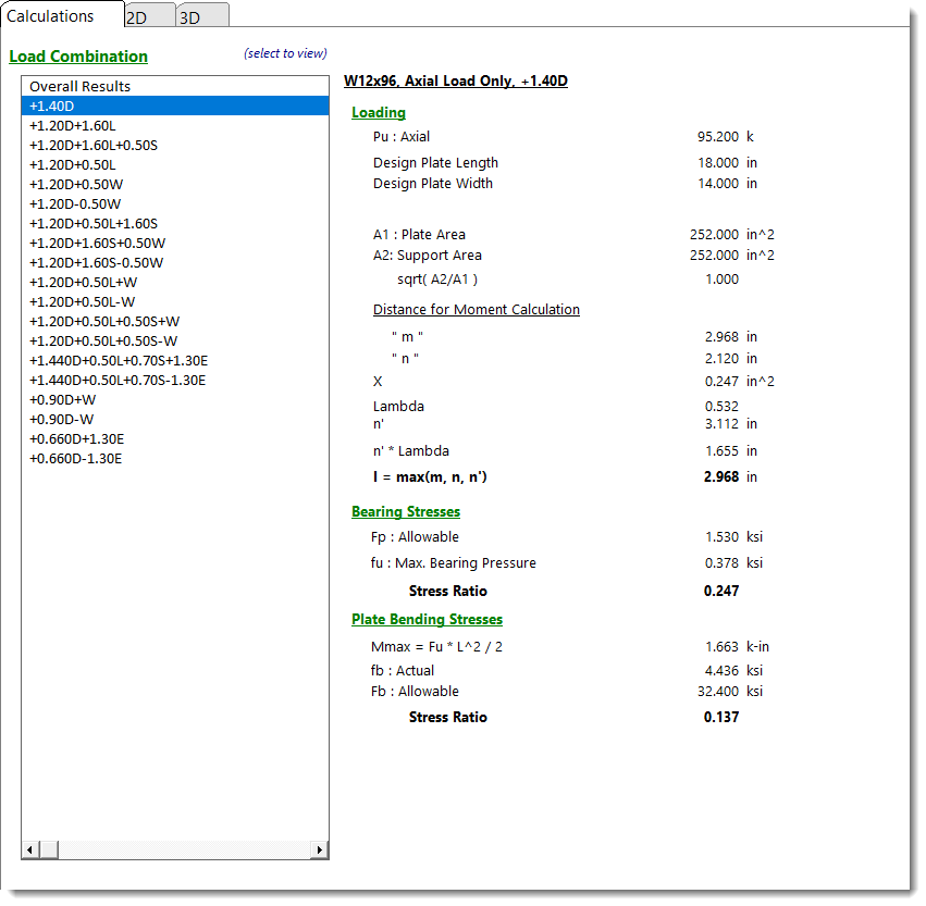
Calculations - Axial Load Only
When the selected load combination results in only an axial load being applied, the summary of information below is displayed. See the AISC Design Guide #1 starting on page 4 for a description of the values present here.
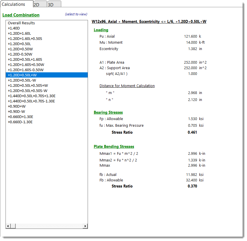
Calculations - Small Eccentricity
When the selected load combination results in an axial load and very small moment being applied, the summary of information below is displayed. This condition is caused when the moment causes the resultant eccentricity of the axial load to be within the middle 1/3rd of the base plate. See the AISC Design Guide #1 starting on page 19 for a description of the values present here.
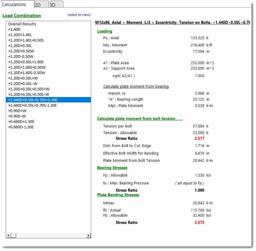
Calculations - Large Eccentricity
When the selected load combination results in an axial load and large moment being applied, the summary of information below is seen. This condition is caused when the moment causes the resultant eccentricity of the axial load to be outside the middle 1/3rd of the base plate. See the AISC Design Guide #1 starting on page 21 for a description of the values present here.
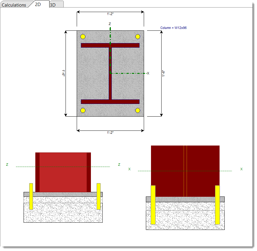
2D Sketch
3D Rendering
