Torsional Analysis of Rigid Diaphragm |
  
|
Torsional Analysis of Rigid Diaphragm |
|
This module provides horizontal force distribution analysis for a rigid diaphragm laterally supported by up to 160 resisting elements (walls, columns or generic resisting elements).
The lateral shear force is applied to the rigid diaphragm, and that force is distributed to all elements after the rotational stiffness analysis has been completed.
All lateral forces are distributed to each element on the basis of relative rigidities and resisting element locations. Lateral shear forces, direct torsional forces, and accidental eccentricity torsional forces are considered after determining the location of the center of rigidity.
The module provides analysis for one level only. For structures where elements are symmetrically placed on many levels, a calculation may be performed for each level and results added to determine shears and overturning moments for each element. When determining center of mass (where the lateral force is applied) on successively lower levels when elements are NOT all aligned vertically, a new center of mass position should be calculated based upon element forces acting from the diaphragm from the level above and combined with the force at that level.
A very unique capability of this module is to have the applied lateral load applied at angular increments for a full 360 degree rotation. The prior version of this module in our Version 5.8 software only applied the lateral load at 90 degree increments. Because seismic or wind loads can occur at any angle, we provide the ability for the user to define the angles at which the lateral load is applied to the rigid diaphragm for distribution to the resisting elements.
When the lateral force is rotated around the specified number of angular increments, the user has two options for specifying the magnitude of the force to consider at each angular orientation. One option is to specify the magnitude of the applied lateral force and an optional orthogonal force magnitude that will be considered to act concurrently. When this option is selected, the program uses the same magnitude for the resultant lateral force at all angular increments, and that magnitude is calculated as the SRSS of the applied lateral force and the orthogonal force. The second option is to specify the magnitude of the applied lateral force when the force points in the X direction and the magnitude of the applied lateral force when the force points in the Y direction. When this option is selected, the program considers the lateral force to vary in an elliptical manner as the angular orientation of the force changes. When the force is considered to act at the zero-degree orientation (to the right on the plan view), the magnitude will be exactly equal to the specified lateral force in the X direction. As the angular orientation changes (positive angles measured CCW from the +X axis), the lateral force will vary in that elliptical manner. When the force is considered to act at the 90-degree orientation, the lateral force will be exactly equal to the specified force in the Y direction, and so on.
Another unique feature is the handling of the accidental eccentricity. The code specifies that an accidental eccentricity must be considered, as it will have an effect on the total torsional moment applied to the diaphragm. The minimum eccentricity is typically specified as 5% of the building dimension measured perpendicular to the direction of load application. To thoroughly address the eccentricity requirements, this module creates an ellipse measuring 5% (or the specified value) of the building dimension on each axis, around which the lateral load is applied.
Technical note: Prior to build 6.15.7.24, this module neglected the shear due to the torsional component of load if it was of the opposite algebraic sign to the direct shear component, because considering that component would reduce the total shear on the particular element being considered. However, build 6.15.7.24 introduced a user option to change this behavior. It appears in the form of a checkbox labeled "Neglect torsional shear component when it reduces total shear in element". If this option is selected, the program will operate in the way that it used to prior to build 6.15.7.24. If this option is DEselected, the program will always consider the shears due to torsion (inherent and accidental), even if they are of opposite algebraic sign to the direct shears and therefore tend to reduce the total shears in an element.
So to recap.....the applied lateral load is applied at the angular increments you specify for a full 360 degrees, and this is performed for the number of angular locations you specify around the minimum eccentricity ellipse. This means if you use 15 degree angular increments for load direction and 15 degree increments for accidental eccentricity, then the lateral load is actually applied (360/15+1) * (360/15+1) = 625 times in various locations and directions. This can provide a very accurate calculation of applied torsions and direct shears to all resisting elements connected to a rigid diaphragm.
Basic Usage
•The most important step for successful use of this module is to properly enter the X and Y location of the center of rigidity of each resisting element and its angle in degrees counterclockwise from a normal Cartesian "0" degree orientation.
•For each resisting element, its center of rigidity will be at the centroid of the element.
•Default angular orientation of elements is as follows:
•Walls: When rotation is zero, length (local y) is parallel to Global X (points right on the screen), and local x points downward on the screen.
•Bending Members: When rotation is zero, local y is parallel to Global X (points right on the screen), and local x points downward on the screen.
•Generic Resisting Elements: When rotation is zero, local y is parallel to Global X (points right on the screen), and local x points downward on the screen.
•When rotation angles are applied to resisting elements, the angle increases positively in a counterclockwise direction. Enter all angles as positive.
•Lateral shears are typically the force at the diaphragm level due to wind or seismic forces at that level. Location of Shear Application specifies the X-Y coordinates of the center of the load ellipse where the lateral shears act. If lateral forces must be added to the diaphragm from the level above or below, you must combine all forces to calculate an adjusted mass application point. Maximum Dimensions are used to calculate the minimum additional eccentricity that will be added to and subtracted from the inherent eccentricity to calculate governing forces for each resisting element.
•When defining walls as resisting elements, the thickness, length, and height are required for each wall providing lateral support to the diaphragm. These values are used with the elastic modulus to establish the relative stiffness of each wall. For other resisting elements you can enter the section information or just enter the resisting element deflection under the same load for all elements.
•The Elastic Modulus does not have to be an exact value if all of the elements are of identical construction. In this situation, it may be simpler to just use a value of 1.
•X & Y Distances for each resisting element define the location of the center of stiffness of each element in plan view. This location will be used when combining all stiffnesses and calculating the overall center of rigidity for all elements acting as a system.
•Enter the fixity condition that best describes the element's top and bottom restraint against rotation about the longitudinal and transverse axes. Fix-Pin would be appropriate for an inverted pendulum condition (where walls or columns cantilever up from a fixed base condition, but are free to rotate at their tops). Fix-Pin would also be appropriate for a moment frame structure with pinned column bases (a structure that behaves like a table). Fix-Fix would be appropriate for conditions where both the tops and the bottoms of the columns and/or walls are fixed against rotation about their longitudinal and transverse axes. This setting results in double curvature in the vertical lateral force resisting elements.
Unique Features
This module uses a numerical approach to determine center of rigidity location and to distribute lateral forces to each resisting element. Because resisting elements may be located at any angle, a rigorous stiffness analysis is performed, calculating each element's stiffness about both axes and combining the stiffnesses of all the elements to determine a center of rigidity location.
Coordinate System
Please note that a strict X-Y coordinate system should be used to ensure that the analysis is properly carried out. When setting up a model, remember that Global X increases to the right and Global Y increases up the screen.
Dimensions & Loads
Loading
Specify Primary & Orthogonal Force
Applied Lateral Force
This is the main force applied to the rigid diaphragm. The location of application is defined by the load ellipse, the center of which is specified in the input item labeled Location of Shear Application.
Additional Orthogonal Force
This is an optional force that is applied at a 90-degree angle to the main force. Some codes specify that this force must be applied concurrently with the main force.
Maximum Load Used for Analysis
This is the resultant force applied to the diaphragm, calculated as sqrt(Main2 + Orthogonal2).
Specify Nonconcurrent X & Y Forces
Applied Lateral Force X Direction
This is the magnitude of the lateral force applied to the rigid diaphragm when the load is oriented at exactly zero or 180 degrees.
Applied Lateral Force Y Direction
This is the magnitude of the lateral force applied to the rigid diaphragm when the load is oriented at exactly 90 or 270 degrees.
When the load orientation is anywhere between the cardinal directions, the magnitude of the applied lateral force is determined by assuming that the lateral force follows a smoothly varying elliptical function.
The location of application is defined by the load ellipse, the center of which is specified in the input item labeled Location of Shear Application.
Load Angular Increment
This module allows the force to be applied to the rigid diaphragm in almost all angular directions.
According to the entry for angular increment, the module will apply the load to the diaphragm at multiple angular increments. For example, if you select "15 deg", the module will apply the lateral load at 0, 15, 30 degrees, etc. When the Load Angular Increment is set to smaller values, it will result in slightly longer calculation times, but it wall also allow the module to "zero in" more accurately on the actual maximum shear forces in all of the resisting elements.
Note that there is also an option named "Specify". This allows you to specify an angular increment for the direction of load.
Accidental Eccentricity Angular Increment
Most building codes require the consideration of an "accidental eccentricity". This is a prescribed additional amount of moment arm that must be compounded with the inherent eccentricity that already exists in the system; i.e. the distance between the center of rigidity and the center of mass for seismic loads or the distance between the center of rigidity and the center of exposure for wind loads. This additional eccentricity accounts for the variability of the exact location of the center of rigidity in normal as-built conditions.
Normally an "X direction" and a "Y direction" accidental eccentricity would be determined as a function (typically 5%) of the overall building dimension perpendicular to each direction. Then, the X directed force would be applied at two locations:
•center of mass PLUS "Y direction" eccentricity, and
•center of mass MINUS "Y direction" eccentricity.
And the Y directed force would be applied at two locations:
•center of mass PLUS "X direction" eccentricity, and
•center of mass MINUS "X direction" eccentricity.
However, in this module the "X direction" and "Y direction" eccentricities are used to specify the dimensions of an ellipse that encircles the center of mass. This ellipse creates a continuous path that smoothly incorporates the "X direction" and "Y direction" eccentricities. In this way, it defines all possible locations where the load should be applied to account for all possible accidental eccentricity locations.
The entry for Accidental Eccentricity Angular Increment specifies the angular increment that will be used to subdivide the ellipse into a number of locations where the force will be applied to the diaphragm.
Summary of Angular Increment & Accidental Eccentricity Angular Increment
The module applies the lateral load at the "Load Angular Increments" at each location of "Accidental Eccentricity Angular Increment" to generate an extensive set of results from which the maximum force values for each resisting element may be inspected.
For example, setting both "Load Angular Increment" and "Accidental Eccentricity Angular Increment" to 15 degrees tells the module to run (360/15 + 1) * (360/15 + 1) = 625 separate analyses of force distributions to the resisting elements.
Location of Shear Application
This specifies the X and Y location of the center of mass. The Accidental Eccentricity ellipse will be circumscribed around this location.
Accidental Torsion Values
Accidental torsion is defined as a percentage of overall constructed diaphragm dimension in each of two orthogonal directions. Therefore enter the necessary eccentricity percentage and both maximum diaphragm dimensions here.
When Stiffness deflections are 0.00, assume completely flexible
Note the option named "When Stiffness deflections are 0.00, assume completely flexible". This option can be used if your intent is to specify that an element is completely flexible in the weak direction. In this situation, you would need to specify an infinite deflection in that direction. So as a convenience, the system has been configured such that when this option is selected, it will interpret a deflection value of 0.00 as meaning that the element is completely flexible in that direction (i.e. has no ability to resist an applied force in that direction).
Resisting Elements
Resisting Element Type
This module allows you to use three types of resisting elements.
Walls: Use the Walls tab to define a wall as a resisting element. The wall must be rectangular in plan and must have a non-zero height. The selections for "Fix" and "Pin" will alter the equation used to calculate deflection in BOTH directions of the wall (unless the option is selected to "Consider all minor axis wall stiffnesses to be negligible"). Using the entered height, length, thickness, and modulus of elasticity for bending and shear, the module will calculate the bending and shear stiffness of the wall and report the deflection for a unit 1 kip applied load.
Note: The option to "Consider all minor axis wall stiffnesses to be negligible" allows walls to be modeled with a weak spring stiffness resisting flexure about the weak axis. It will tend to minimize the stiffness of walls about that axis, so they will not pick up much loading in the weak direction.
Bending Members: Use the Bending Members tab to define a bending member (such as a column) as a resisting element. This will be a linear member whose stiffness is specified simply by its X and Y axis moments of inertia. You must also provide a value for the modulus of elasticity of the Bending Member for bending. Finally, you must make a fixity selection, which dictates the equation used to calculate deflection in BOTH directions of the member (unless the option is selected to "Consider all minor axis beam stiffnesses to be negligible"). Using these settings, the module will calculate the bending stiffness of the member and report the deflection for a unit 1 kip applied load.
Generic Resisting Elements: Use the Generic Resisting Elements tab to specify a generic resisting element whose lateral deflection is known for an applied 1 kip load. This selection is intended for complex resisting elements like braced or moment frames, where another analysis module has determined the unit deflection.
Add Element & Delete Element Buttons
Use the [Add Element] and [DeleteElement] buttons to add a new resisting element or delete the one currently highlighted in the list.
Element Data
This area allows you to specify a label and location of the center of resistance for a resisting element.
Resisting Element List
This is the list that you create to define the resisting element locations that give lateral force resistance to the rigid diaphragm.
This table serves to give a summary of the deflections, location and major axis angle for each element. When you click to highlight a line in the table, the information for that resisting element is brought into the variables on the input area.
Summary Maximums
Please note that a STRICT X-Y coordinate system should be used to ensure that the analysis is properly carried out. When setting up an X-Y coordinate axis, please follow the standard Cartesian model with the diaphragm.
Recall that the module calculates the forces to each resisting element by rotating the force about its point of application. That point of application is in increments around an accidental eccentricity ellipse.
This Summary Maximums tab provides the maximum forces for each resisting element along the major and minor axis of the element.
Force Envelope Detail
This tab provides the main table that shows all of the force calculations for each resisting element. It is tree structured, so clicking the [+] sign to the left of each item name will expand the result set for that item.
In the image below we see that the data for the wall labeled "D" is expanded. Below "Label : D" we see many lines labeled "0 deg". These are the results for the load applied at an orientation of 0 degrees. On each "0 deg" line, observe that the "X Ecc" and "Y Ecc" values are changing. These values are the locations of the applied load as it moves its way around the accidental eccentricity ellipse. The note at the top of the table indicates that the analysis is based on 15-degree "Eccentricity Location" increments. This implies that there will be (360 degrees/15 degrees) = 24 lines of data based on the "0 deg" force orientation. Then, if we scrolled down through the table, we would see that the load application angle has also been set to change in 15-degree increments as well.
Note that direct shear is always considered as a positive value, and the algebraic sign on the torsional shear component will be positive if its effect is additive to the effects of the direct shear, or negative if its effects are subtractive from the direct shear. The algebraic sign on the torsional shear component does NOT indicate its direction with respect to the overall Cartesian coordinate system.
2D Sketch
3D Rendering
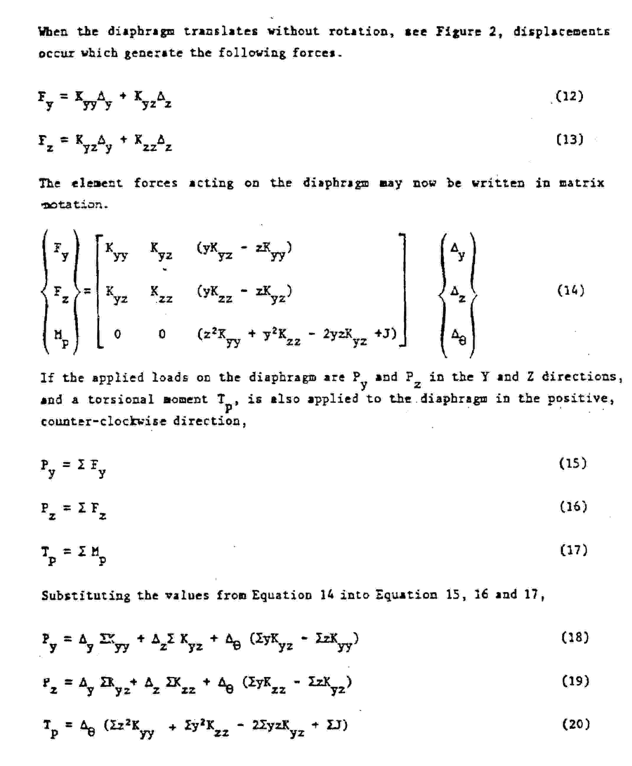
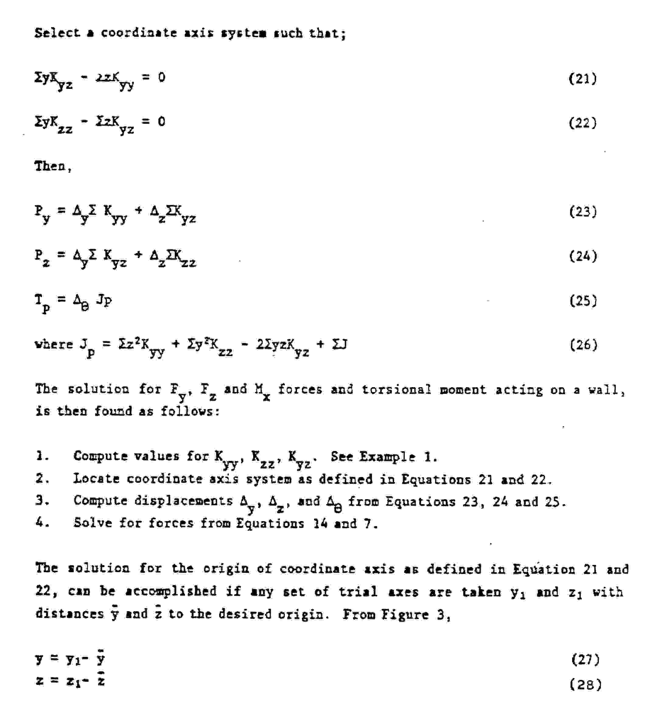
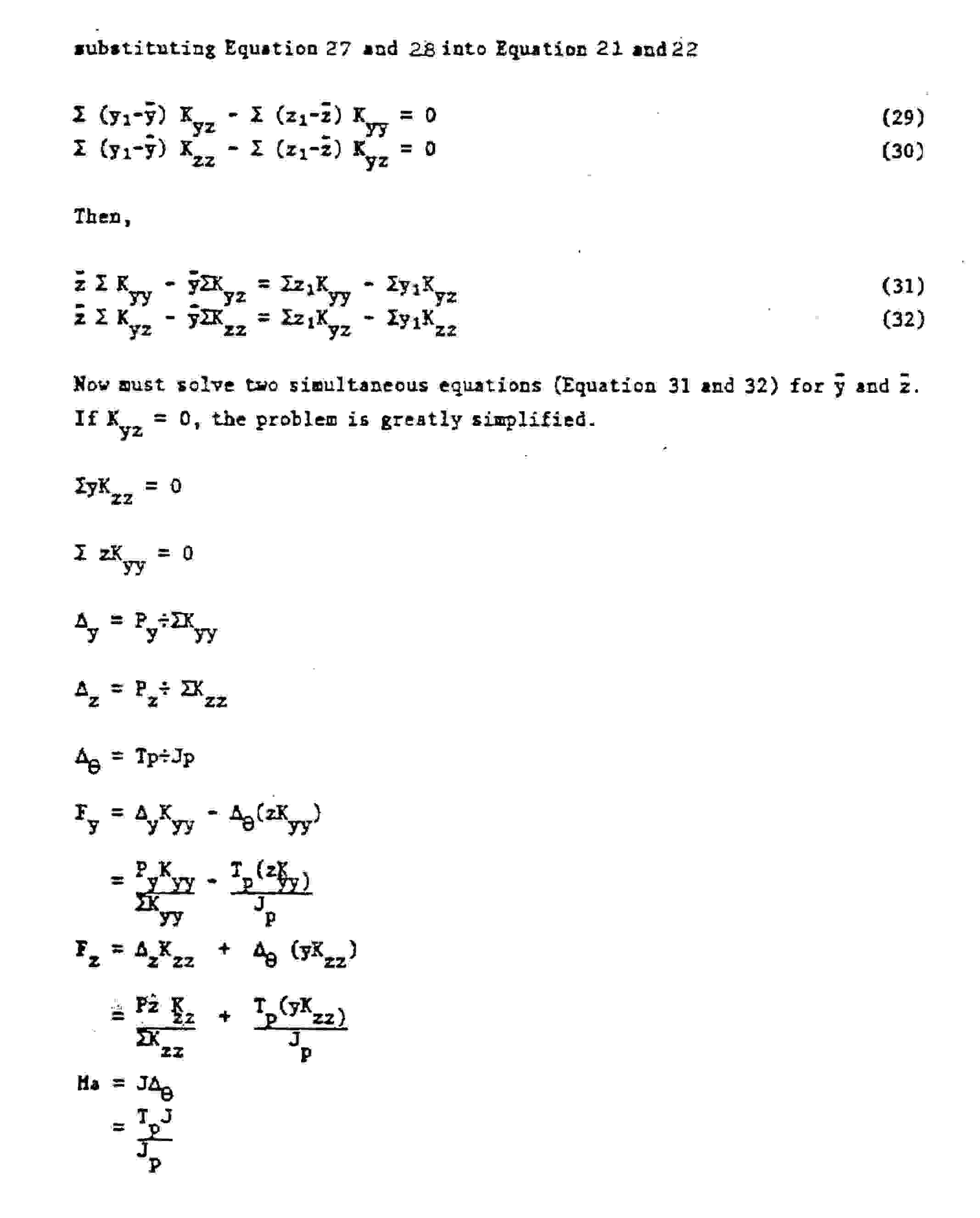
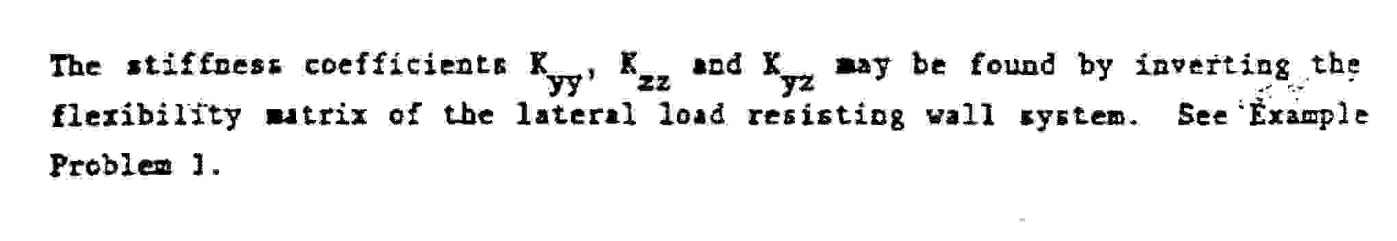
Analysis Procedure
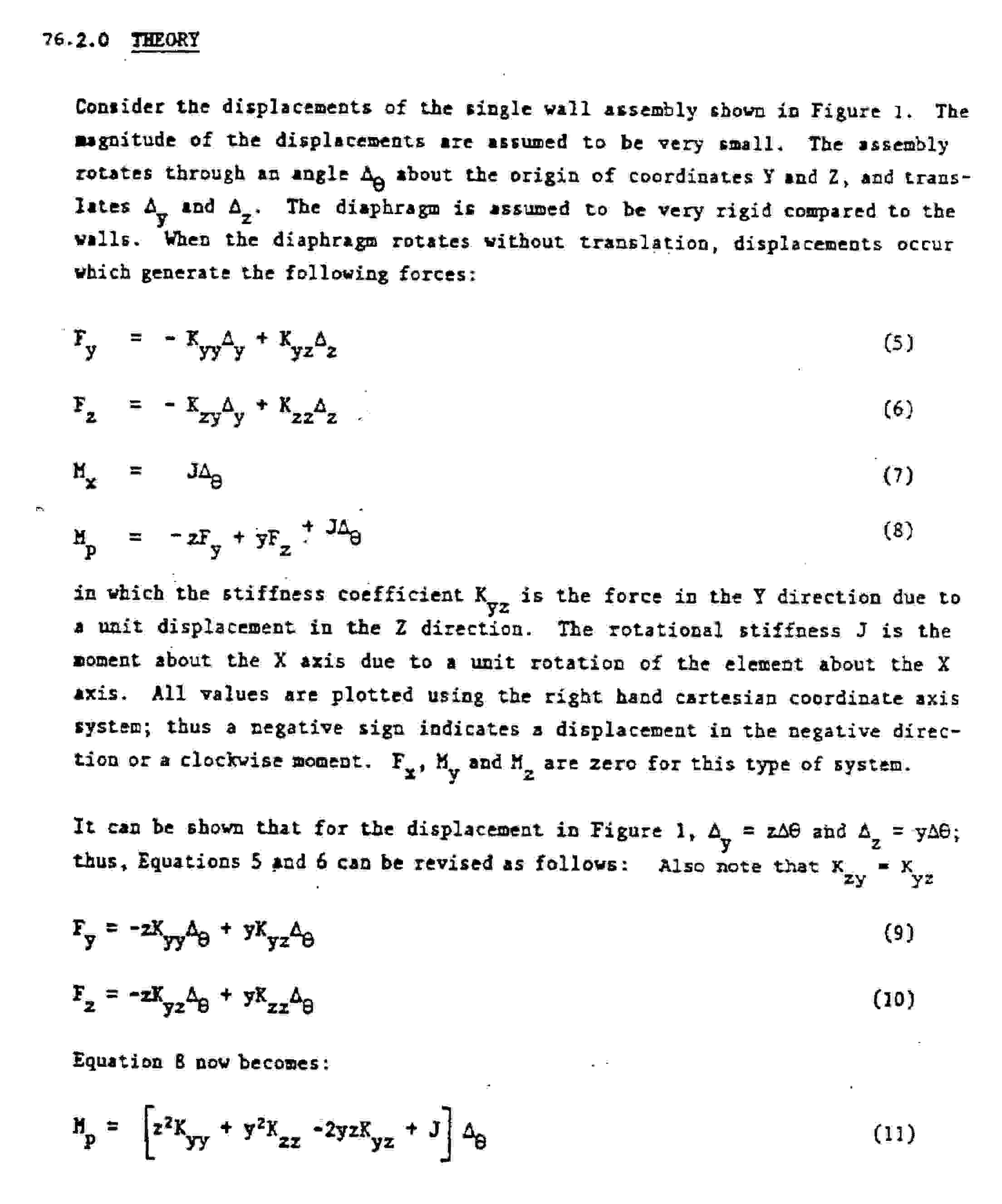
Please see the following description for the procedure used to calculate the system stiffness matrix and resolve the forces for each resisting element.
 <
<