Wood Beam |
  
|
Wood Beam |
|
In this section, for each input tab we will review only the items that are unique to the WOOD material type.
For general information on the typical data input for all beams see the Beams topic.
This module offers complete design of single and multi-span wood members. Among its capabilities are:
•Single or multi-span beams.
•End fixity can be pinned, fixed, free or a combination thereof.
•Analysis is according to NDS.
•ASD or LRFD design methods can be selected. Values of KF and phi are automatically determined and applied for the LRFD method.
•A complete wood section database is provided. This includes sawn, glued-laminated and selected engineered wood products.
•A complete wood species database is provided. All values are per the latest NDS.
•Unbraced compression edge lengths can be specified in a variety of ways.
•Automatic member selection is provided.
•You can specify values for CM, Ct and Cr.
•CF or CV is automatically provided. In the case of CF, the value is also based on species stress grade. Note: 2018 NDS allows Cv to be greater than OR less than 1.0 for EWP. But some EWP manufacturers limit their values of Cv to be <= 1.0. So as of January 12, 2023, ENERCALC SEL conservatively limits the value of Cv to be <= 1.0 for EWPs.
Beam Material
Clicking one of these buttons changes the material type used for the beam.
Design Method
For wood & steel you can select ASD or LRFD design methods. Concrete design always uses ultimate strength design (LRFD).
Design Values
This section is used to specify the type of wood that will be used. Use the ![]() button to access the standard wood reference design values database and select a material.
button to access the standard wood reference design values database and select a material.
These values can be edited right on the screen. HOWEVER there are other pieces of information, such as size factors for certain sizes of members, that are stored separately.
This tab is used to define span length and section information for the beam:
The button indicated in the screen capture below is used to display the Wood Section Database.
The Wood Section Database contains an extensive number of solid-sawn members, glulam members, and engineered wood products commonly used in the USA.
The button shown bubbled in the screen capture below is used to display the Wood Member Design dialog.
The Wood Member Design dialog allows you to choose the type of member to be selected and to specify limits on the permissible stress ratio, deflection ratio and selected member size.
Note: The factor named Maximum Stress Ratio does not act as a multiplier on the specified deflection ratios.
No differences from other materials.
No differences from other materials.
For wood members you will see entries for load duration factors. When ASD is used, the Load Duration Factor is referred to as CD. When LRFD is used, the Load Duration Factor is referred to as λ.
Note that CD and λ can be automatically set for all load combinations by clicking the Auto Set button button at the top of the column of values. When that button is clicked, the program will automatically determine the proper value for CD or λ according to the NDS based on the shortest duration load type included in each of the load combinations.
Results Tabs: This set of tabs provides detailed results for the current calculation. The tabs in the upper right-hand corner of the screen allow you to select the major areas available for review: Calculations, 2D Sketch, Diagram and 3D Rendering.
The Calculations tab offers the following results options:
Summary Results provides details for shear, moment and deflection for the governing load combinations.
Max. Combinations provides detailed results for each beam segment for each load combination. The leftmost column lists the load combinations and the unbraced length being considered.
These results are a consolidation of the highly detailed incremental results presented on the M-V-D Summary tab.
M-V-D Summary - Shears & Moments shows highly detailed moment and shear information for each beam and for each load combination. For multi-span beams using Automatic Unbalanced Live Load Placement there may be thousands of lines of results.
M-V-D Summary - Deflections shows highly detailed deflection results for all load combinations.
Support Reactions shows reactions for each support for each load condition.
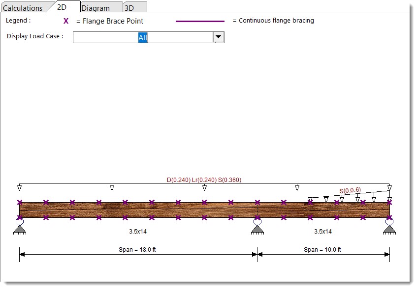
The 2D Sketch tab provides a graphic representation of the beam currently being designed:
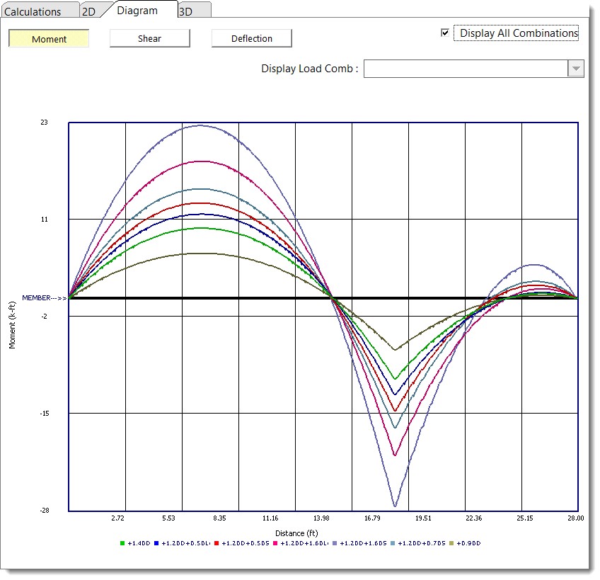
The Diagram tab offers the ability to view shear, moment, and deflection diagrams for selected load combinations:
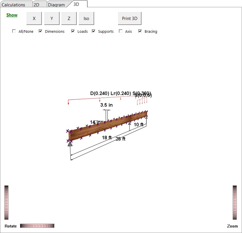
The 3D Rendering tab provides a graphic representation of the beam currently being designed, and offers many display options:
REPORTS
Below is a typical Wood Beam printed report:
 <
<