|
Cantilevered Retaining Wall |

|

|

|

|

|
|
|
Cantilevered Retaining Wall |
|
|
|
|

|
Cantilevered Retaining Wall
|
Cantilevered Retaining Wall |
|
|
|
|
|
|
|
Cantilevered Retaining Wall |
|
|
|
|
|
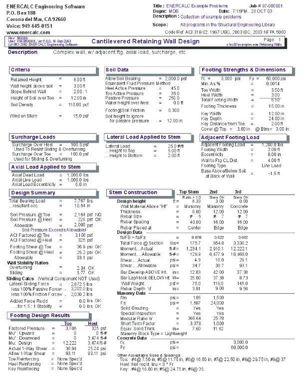
This program provides calculation procedures necessary to perform complete design and analysis of a conventional cantilevered retaining wall.
The retaining wall may be loaded with any of the following load combinations :
| • | Any angle of sloped backfill. |
| • | Surcharge loading above heel or toe. |
| • | Eccentric axial dead and live load on stem. |
| • | Lateral and vertical load from an adjacent footing. |
| • | Wind or seismic force on projecting portion of stem. |
| • | An additional uniform lateral load may be applied to the wall. |
The following overall dimensions can be specified:
| • | Retained height. |
| • | Toe and heel dimension. |
| • | Wall extension above retained height. |
| • | Footing key depth, width, and location. |
| • | Soil height over the toe. |
The following stability checks are performed:
| • | Total overturning and resisting moment. |
| • | Optional Inclusion of vertical active pressure on the rear face of the wall to resist overturning. |
| • | Sliding resistance using both passive and active pressure. |
| • | Both heel and toe of the footing are designed as follows: |
| • | Toe Design - Find actual moment at stem face, check required minimum reinforcing, list rebar choices, and check one-way shear. |
| • | Heel Design - Find moment at stem face, check required minimum reinforcing, list rebar choices and check one-way shear. User may neglect upward soil pressure for conservative design. |
Stem Design: Up to five ascending stem sections, either masonry or concrete, may be selected. User enters whether masonry or concrete, thickness, rebar size and location, and special inspection status. Program determines maximum rebar spacing (at 8" modules for masonry), and checks shear at bottom of section
Also, the program has the unique ability to design screen walls (freestanding walls where the retained height is low and the projection above the soil is higher). Wind and seismic loads may be applied to the projecting portion, and an increased allowable stress may be used as allowed for short term loadings.
Basic Usage
| • | Entering Soil Data specifies the lateral earth pressures applied to the wall. Active Pressure will be used on over toe and/or heel unless Slope is non-zero. If this is the case, then the soil is sloped and Slope Pressure will be used behind the wall to generate lateral loads. Maximum Pressure can be entered to instruct the program to limit the lateral pressure intensity. (The pressure diagram then becomes uniform). Passive Pressure will be used for the full depth of soil in front of the wall to resist sliding. Soil Density will be used for soil weight, and Soil Height Over Toe will be used to define passive pressure height, vertical load, and will create an active pressure resisting overturning. |
| • | You can apply two additional vertical Loads: an Axial Load to the top of the stem (with optional eccentricity), and Toe and Heel Surcharges. If the heel surcharge is permanent, you can specify that it Should Be Used To Resist Overturning. |
| • | In addition to the lateral loads created by the soil above the footing, you can apply additional Lateral Loads to the wall. Enter a Lateral Loads Acting on the Stem Above Soil when your wall will extend above the soil, such as a screen or guard wall. Impact and bracing loads can be applied to the wall using the Additional Lateral Load item, letting you specify a load intensity and length. You can also enter an Adjacent Footing Load, by specifying the magnitude of load and position relative to the rear of the topmost stem section. |
| • | The Wall and Footing Data section is used to specify the retained height, stem height above soil, and footing dimensions. Zero entries are permitted for the key and either toe or heel width. While using the program, you can easily change these values often and recalculate [F9] to determine soil pressures, overturning stability, and sliding stability. |
| • | The critical footing wall design values are given in the Summary area, where you can review calculated results and then modify the wall and footing data as required. |
| • | The program will perform a Sliding Check when you enter Footing/Soil Friction coefficients, and can Neglect a certain height of soil, if the soil in front of the wall is non-compacted. |
| • | By simply entering the concrete strength, steel strength, and minimum steel percentage the program will provide a full Footing Analysis and Rebar List. |
| • | Stem Design can be performed for up to five independent sections of the wall. By specifying Wall Construction Type, Design Height, and Wall Thickness and Reinforcing, each stem section can be easily refined for an optimum design. |
| • | The Summary of Overturning and Resisting Moment table should be reviewed if you have any questions on how the vertical and lateral loads are being applied to the wall. |
| • | When you are satisfied with the wall, Print or Save the current worksheet, choose Reset to start another wall design, or use the Access Menu to choose another program. |
Unique Features
| • | Slope of backfill may be varied from flat to 45 degrees. |
| • | Either a concrete or masonry stem can be specified. When concrete is chosen, the wall thickness, rebar size, and location is used to calculate the minimum spacing for the rebar. When masonry is specified, the option of special inspection is entered in addition to the above values, and the maximum rebar spacing is calculated at 8" modules. |
| • | The program has the unique ability to design screen walls for conditions where the wall extends a distance above the soil which is much greater than the retained height. |
Assumptions & Limitations
| • | Both active and passive pressures are applied as Equivalent Fluid Pressures. |
| • | Friction coefficient is assumed to be applicable for both friction only and friction combined with passive pressure cases. |
| • | Design for bending reinforcement in Toe and/or Heel of footing is calculated using d = thickness minus 3". |
| • | If surcharge exists above the Toe or Heel, the soil height over those areas will be increased (internally) by the ratio of Surcharge/Soil Density. |
| • | All concrete design is based on ACI Ultimate Strength Design. |
Example
The data entry for this example is shown in the screen captures that accompany the Data Entry Tabs and Results & Graphics Tabs sections to follow.
Data Entry Tabs
This set of tabs provides entries for all input in this calculation. While you are entering data and switching between these tabs you can view the desired resulting information on the tabs on the right-hand side of the screen (calculated values, sketches, diagrams, etc.). A recalculation is performed after any entry data is changed. After each data entry you can view the results on the right-hand set of tabs.
General Data Tab
Retained Height
This is the height of retained earth measured from top of footing to the top of soil behind the stem (over the heel). When the backfill is sloped, the soil will slope away and upwards from this height. The actual retained height used for overturning and soil pressure calculations will be the retained height projected at the vertical plane of the back of the heel, but for stem moments, no such increase will be made. Using the spin-buttons you can vary this in 3-inch increments (you can type in any number). After each entry you can press the tab key to advance to the next entry, or use your mouse to position the cursor.
Wall Height Above Retained Soil
Use this entry to specify if the wall extends above the retained height. This entry is typically used to define a "screen wall" projection above the soil retained. This extension can be used as a weightless "Fence" or a concrete or masonry stem section without any soil retained behind it. You can enter wind load on this projection using the entry "Load @ stem above soil" on the "Loads" tab. We'll handle the fence when we get to the STEM design screen.
Height of Soil Over Toe
Measured from the top of footing to top of soil, this may vary from a few inches to a few feet (it is measured in inches) depending upon site conditions. It is used to calculate passive soil pressure depth (considering "Ht. to Neglect" on "Sliding" tab). This soil can also be used to calculate an active pressure to reduce overturning; this is a choice on the Options Screen, and can have significant effect if the footing is well below grade.
Water Table Height Over Footing
If you want to design for a water table condition, enter the maximum height from top of footing to water table level. The program will then compute the added pressures for saturated soil on the heel side of the footing, including buoyancy effect, to calculate increased moments and shears on the stem, and overturning. Do not enter a height greater than the retained height, nor a liquid other than water.
Soil Slope
You may enter any backfill slope behind the wall. Use the drop-down menu or type the slope ratio as Horiz/Vert. The soil must be level or slope upward. Negative backfill slopes (grade sloping downward, away from the wall) are not allowed.
The program will use this slope to 1) include the weight of a triangular wedge of soil over the heel as vertical load, and 2) compute overturning based upon an assumed vertical plane at the back face of the footing extending from the bottom of the footing to ground surface - a steeper slope will result in a higher overturning moment. We suggest not using a slope steeper than 1.5 to 1.0 unless approved by the geotechnical engineer. The program will not accept a backfill slope steeper than the angle of internal friction.
Allowable Soil Bearing
The maximum allowable soil bearing pressure for static conditions. Using the spin buttons you can increment in 50 psf steps. Usual values for this vary from 1,000 psf to 4,000 psf or more.
Lateral Pressure Method
Here you can choose between E.F.P. or Rankine formula or Coulomb formula. EFP means "Equivalent Fluid Pressure," where you can enter a lateral soil pressure in psf per foot of depth. "Rankine" or "Coulomb" instructs Retain Pro to use the Rankine or Coulomb Method to calculate active and passive soil pressures using an entered angle of internal friction for the soil. When Rankine or Coulomb is chosen, the Ka*Density value for active pressure is computed.
Active Soil Pressure - Heel Side (EFP Method Chosen)
Active Pressure: Ka * Gamma (Rankine or Coulomb Method Chosen)
Enter the equivalent fluid pressure (EFP), or the angle of internal friction if Rankine or Coulomb is chosen, for the soil being retained that acts to overturn and slide the wall toward the toe side. This pressure acts on the stem for stem section calculations, and on the total footing+wall+slope height for overall stability and soil pressure calculations.
Commonly used values, assuming an angle of internal friction of 34, are 30 pcf for a level backfill; 35 pcf for a 4:1 slope; 38 pcf for a 3:1 slope; 43 pcf for a 2:1 slope; and 55 pcf for a 1.5:1 slope. These values are usually provided by the geotechnical engineer. If the Rankine or Coulomb method had been chosen, these values will be computed using those formulas.
When the retained soil is sloped, a vertical component of the lateral earth pressure over the heel can be applied vertically downward in the plane of the back of the footing. You can choose to apply this force for overturning resistance, sliding resistance, and/or for soil pressure calculations, by checking the boxes on the CRITERIA > Option screen.
Angle of Internal Friction (Rankine or Coulomb Method Chosen)
This value is entered in degrees and is the angle of internal friction of the soil. This value is usually provided by a geotechnical engineer from soils tests, but can also be found in reference books or building codes for various typical soil classifications. This value is used along with Soil Density within the standard Rankine and Coulomb equations to determine "Ka" and "Kp" multipliers of density to give active and passive soil pressure values.
Active Soil Pressure - Toe Side
If the EFP method is chosen, enter the active pressure to be used on the toe side of the wall. This active pressure is used along with the "Soil Height over Toe" value (entered on the Sliding tab) to calculate a stabilizing soil force on the wall. This front side of the wall is assumed to be level.
When either the Rankine or Coulomb method is chosen, the angle of internal friction is used in the Rankine formula with an assumed level toe-side slope.
The active pressure from soil over the toe partially counteracts the heel-side active pressure for overturning calculations.
Passive Pressure (EFP Method Chosen)
Passive Pressure: Kp * Gamma (Rankine or Coulomb Method Chosen)
This is the resistance of the soil in front of the wall to being pushed against to resist sliding. Its value is in psf per foot of depth (pcf). For the E.F.P. method, you input this value, which is usually obtained from the geotechnical engineer. If the Rankine or Coulomb method is chosen, it will be computed and entered for you. Its value usually varies from 100 pcf to about 350 pcf.
Soil Density
Enter the soil density for all earth above the toe and heel of the footing. This weight is used to calculate overturning resistance forces and soil pressures using the weight of the soil block over the projecting toe and heel of the footing. When surcharges are applied over the soil, the surcharges are transformed to equivalent uniform lateral loads acting on the wall by the ratio force = (Surcharge/ Density)*Lateral Load. Input this value in lbs. per cubic foot. Usual values are 110 pcf to 120 pcf.
Material Data Tab
This screen allows you to change properties of masonry and concrete. It also allows you to decide what load factor (1.4 or 1.7) to use for factored soil pressure attributable to dead loads.
For Masonry
Concrete Block Type
This allows you to select Lightweight, Medium weight, or Normal weight concrete masonry units.
Factor Applied to ![]() for Calculation of Em
for Calculation of Em
The modulus of elasticity for masonry is 750 ![]() (UBC '97 2106.12.1). This entry allows you to select a multiplier other than 750.
(UBC '97 2106.12.1). This entry allows you to select a multiplier other than 750.
Multiplier Applied to Wall Weight from Tables
This entry allows you to increase or decrease the internal default values of stem weights, as displayed on the STEM screen.
For Concrete
Stem concrete weight
This is usually 145-150 pcf, but may be changed with this entry.
Footing concrete weight
This option is necessary since if there is any buoyancy effect, this will reduce the effective weight of the footing concrete.
ACI Factored Soil Pressure
This gives you two choices for computing the factored moment in the toe. Select either a 1.7 load factor for both dead load and pressure attributable to live load and lateral soil pressure on the wall. Alternatively, and less conservative, use a load factor of 1.4 for dead load (footing and superimposed earth) and 1.7 for live load and upward soil pressure attributable to lateral soil pressure.
Options Tab
This screen is critical to your design, since many subsequent calculation results will be affected. Review and check these boxes carefully.
Slab is Present to Resist all Sliding Forces
Check this box when a slab is in front of the wall to resist lateral sliding. This negates sliding concerns (but check the slab if necessary). For restrained wall footings, it deletes the lateral force (base stem reaction) applied to the top of the footing, puts "not applicable" in the sliding ratio display, and dims the sliding entries on the FOOTING > KEY DIMENSIONS AND SLIDING sub-tab screen. The slab restraint is assumed to be at the top of the footing and the program does not allow it to be placed higher-if this condition occurs, append your printout with hand-calcs,
Use Toe Surcharge to Resist Sliding and Overturning
Checking this box will include the weight of soil overburden on the toe to resist overturning and add to its weight for frictional resistance.
Use Heel Surcharge to Resist Sliding and Overturning
Checking this box will include heel surcharge. If surcharge is live load and its use would be non-conservative, don't check this box.
Neglect Upward Pressure at Heel
For heel calculations you may choose to neglect the upward soil pressure, typically resulting in greater heel moment. If this box is checked the Mu for upward loads will be zero.
Toe Active Pressure Used
Checking this box will apply the toe side active pressure to reduce overturning moment and reduce sliding force to a net sliding force to be resisted.
Choices for Use of Vertical Component of Active Pressure
The vertical component of the lateral pressure is applied at a vertical plane at the back of the footing. You can optionally use this to resist overturning, sliding, or for soil pressure calculations. (For the latter it can make a considerable difference). Checking these boxes applies the options. For a level backfill, this option will back-solve the EFP method to find the equivalent internal friction angle, then apply this vertical component equal to tan. If either the Rankine or Coulomb method had been chosen, this vertical component would be tangent of ![]() .
.
Note that most texts suggest using the vertical component only to resist overturning. For a level backfill these options are usually not used.
Loads / Vertical Loads Tab
Additional loads on the wall are entered on these sub-tabs.
Surcharge Over Toe
If other loads are imposed directly above the toe (such as a slab, storage, or moving load), these may be entered here (you have already entered the height of the soil over toe). This surcharge is divided by soil density and multiplied by active pressure to calculate an equivalent lateral load. This surcharge is used to calculate soil pressure. You can use this surcharge to resist sliding and overturning by clicking the box on the CRITERIA > Options sub-tab.
Surcharge Over Heel
This surcharge is considered uniformly applied to the top surface of the retained soil (over the heel). It may be entered whether or not the ground surface is sloped, but is always taken as a vertical force. This surcharge is divided by the soil density and multiplied by the Active Pressure to create a uniform lateral load applied to the wall. You can use this surcharge to resist sliding and overturning by clicking the box on the CRITERIA > Options sub-tab.
Axial Loads Applied to Top of Stem
These loads are considered uniform load along the length of the wall. They are applied to the top of the topmost stem section and effect the design of masonry stems only. The dead and live loads are used to calculate stem design values and factored soil reaction pressures used for footing design. Only the dead load is used to resist overturning and sliding of the retaining wall.
Axial Load Eccentricity
This is the eccentricity of the axial load with respect to the centerline of the uppermost stem section. The eccentricity moves the load toward the toe, causing bending moments that are additive to those caused by the lateral soil pressure over the heel (negative eccentricities are not accepted).
Adjacent Footing Load
This entry gives you the option of placing a footing adjacent and parallel to the back face of the wall, and have its effect on the wall included in both the vertical and horizontal forces on the wall and footing. Refer to the General Reference Diagram for locations where input measurements should be taken.
For a "Line Load" the load entered is the total load per foot parallel to the wall (not lbs. per sq. ft).
If the adjacent footing is specified as "Square Footing" (not line load), the load entered should be the adjacent footing load divided by its dimension parallel to the wall, giving a pounds per lineal foot value, as for a continuous (line) footing.
A Boussinesq analysis is used to calculate the vertical and lateral pressures acting on the stem and footing. The program uses an assumed Poisson ratio of 0.3. (See Foundation Analysis and Design, 5th Edition, by J. E. Bowles, McGraw-Hill, pages 629-639)
Use of the Adjacent Footing may not be applicable if the horizontal distance from back face to stem to closest edge of adjacent footing is greater than the distance from top of wall footing to bottom of Adjacent Footing (i.e. outside an assumed line of influence).
When the Boussinesq analysis is used, the program may require additional computing time, depending upon the speed of your computer. To avoid this delay (which occurs any time any entry is changed) we suggest you use a vertical load of zero until your data entry is nearly finalized. Then enter the actual footing load and modify your final values.
Suggestion: For adjacent truck or highway loading, it may be preferable to use a heel surcharge (uniform) of 250 psf (or more) instead of treating it as an "adjacent footing."
Do not use this feature if the adjacent footing load is farther from the stem than the retained height, less the depth of the adjacent footing below the retained height, since at this distance it will not have significant effect on the wall.
Footing Width
Width of the adjacent footing measured perpendicular to the wall. This is necessary to create a one-foot long by Width wide area over which the load is applied.
Footing Eccentricity
This entry is provided in case the soil pressure under the adjacent footing is not uniform. Enter the eccentricity of the resultant force under the adjacent footing from the centerline of the footing. Positive eccentricity is toward the toe, resulting in greater pressure at the side of the adjacent footing closest to the stem. The program will use the vertical load and eccentricity and create a trapezoidal pressure distribution under the adjacent footing for use with the Boussinesq analysis of vertical and lateral pressures.
Wall to Footing Centerline Distance
Distance from the center of the adjacent footing to the back face of the stem at the retained height.
Footing Type
This drop down menu selection allows you to enter either an isolated footing using the "Square Footing" selection, or a continuous footing using the "Line Load" selection.
Base Above/Below Soil at Back of Wall
Use this entry to locate the bottom of the footing with respect to the Retained Height. Entering a negative number places the footing below the soil. A positive entry would typically only be used when the soil is sloped and the footing resides "uphill". To insert a negative number, first type the number then press the "-" (minus) sign.
Note: If the "Adjacent Footing" is another retaining wall at a higher elevation, the Boussinesq analysis may be used for the vertical load applied to the soil from the wall, however the design must also consider the lateral (sliding) loads from that adjacent wall. This load could be applied as "Added Lateral Load", however this is at the discretion of the designer and is not within the scope of the program. Caution is urged for this condition. See discussion in the companion book: Basics of Retaining Wall Design.
Loads / Lateral Loads Tab
Load @ Stem Above Soil
This load (typically a wind load) will be applied to that part of the stem projecting above the retained height defined by the entry "Wall height above retained soil." It is used to calculate overturning moment and shear, stem design moment and shear, and soil pressures. Customary values are 10 psf or higher. Only a positive "+" value can be entered (i.e., the force may only be applied in a direction to add overturning, in the direction of the active soil pressure).
Added Lateral Load
This input allows you to specify an additional uniformly distributed lateral load applied to the stem. You can use it to apply a seismic load to the wall, an additional uniform lateral load due to soil pressure, or apply a short but intense load due to impact of a car or similar force (this case can be modeled by separating the "Height to Bottom" and "Height to Top" by just one foot, and using an "Added Lateral Load" equal to the total added force). This load is factored by 1.7 to calculate concrete moments and shears.
Height to Top
This dimension defines the upper limit of the added lateral load measured from the top of the footing. Do not enter a dimension higher than the top of the wall ("retained height" plus "Wall height above retained soil").
Height to Bottom
This dimension defines the beginning (or bottom) of the added lateral load measured from the top of the footing.
Stem Tab
The layout of this screen will change depending upon whether you previously chose a conventional cantilevered wall, a tapered stem wall (earth side battered), or a gravity wall. This screen is for a straight stem non-battered wall.
Material
Use the drop down menu to select Masonry, Concrete, Fence, or None. Fence is only allowed on top of the wall, higher than the Retained Height, and is considered weightless. Use None to disable the stem section.
Thickness
Use the drop down menu to input the wall thickness. If masonry is chosen, you will be given standard masonry thickness (e.g. 6", 8", 12"). If concrete is chosen, you can increment in one-inch steps. If Fence had been chosen, this entry is unavailable since the fence is assumed to be weightless.
Wall Weight
This displayed value is based upon the wall data entered earlier. The industry standard values used by the program may be modified on the CRITERIA > Materials Screen. See Appendix C for masonry wall weights.
Rebar Size
Make your selection from the pull-down menu for bar sizes #3 to #10.
Rebar Position
Chose between Center and Edge. If Center is chosen, the rebar d distance will be 1/2 the actual wall thickness. If Edge is chosen it will be located at the heel side of the stem.
For masonry design, the program contains a table of the appropriate "d" values to use for various block sizes and center/edge locations
For concrete, the "edge" rebar depth is always stem thickness less 1.5" for #5 and smaller bars (or 2" for #6 or larger), less one-half the bar diameter. You can modify the rebar depths by using the CRITERIA > Material screen.
Specify Position Box
Clicking this box displays the default "d" value, which may change. If unchecked, the default "d" is displayed.
![]()
Enter ![]() for masonry stems to be designed. This value is not visible when a concrete wall has been specified. Spin button changes this value in 250 psi increments.
for masonry stems to be designed. This value is not visible when a concrete wall has been specified. Spin button changes this value in 250 psi increments.
Fs
Enter the allowable steel stress, based on working stress design, which should be used for design of the masonry stem section. Spin button changes this value in 1,000 psi increments. This value is not visible when a concrete wall has been specified.
Short Term
This is used for masonry design only, and indicates the allowable overstress multiplier (1.33 for wind and seismic, per ACI and UBC). We recommend using a value greater than one only if resulting stresses from wind or seismic are greater than those from static forces acting alone. You select from the pull-down menu.
Special Inspection
This is applicable to masonry stems only, and if checked, the full allowable ![]() used in flexure, shear, and axial stress will be used. If not checked, the allowable values will be reduced by one-half. The Uniform Building Code requires this reduction if Special Inspection is not provided.
used in flexure, shear, and axial stress will be used. If not checked, the allowable values will be reduced by one-half. The Uniform Building Code requires this reduction if Special Inspection is not provided.
Solid Grout
This applies to masonry only, and if this box is checked the weight of the wall will be based upon industry standard solid-grout weight for either lightweight, medium weight, or normal weight. If this box is not checked, the program will calculate the weight based upon grouting of only cells containing reinforcing.
This also affects equivalent solid thickness for stem shear calculations, and area for axial stress calculations (combined with moment for masonry stems).
Modular Ratio "n"
This is the multiplier used on ![]() to calculate the modulus of elasticity of masonry. The 1997 UBC specifies Em = 750 *
to calculate the modulus of elasticity of masonry. The 1997 UBC specifies Em = 750 * ![]() , which is the default value in the program. ACI 530-02, Table 5.5.1.3, lists higher values, which result in lower "n" values, hence the allowance for the user to modify it by using the CRITERIA > Material screen.
, which is the default value in the program. ACI 530-02, Table 5.5.1.3, lists higher values, which result in lower "n" values, hence the allowance for the user to modify it by using the CRITERIA > Material screen.
Equivalent Solid Thickness
If partially grouted (not solid grout) this value is generated from an internal database as shown below:
Masonry Equivalent Solid Thickness (inches)
Grout Spacing
Thickness (inches) 8" 16" 24" 32" 40" 48"
6 5.6 4.5 4.1 3.9 3.8 3.7
8 7.6 5.8 5.2 4.9 4.7 4.6
10 9.6 7.2 6.3 5.9 5.7 5.5
12 11.6 8.5 7.5 7.0 6.7 6.5
14 13.6 9.9 8.7 8.1 7.6 7.4
16 15.6 11.6 10.1 9.5 8.6 8.3
Stem Design Heights
IMPORTANT! The term "Design Height" used in this program is the height above the top of the footing (i.e. base of stem) where you want to check the design. It calculates moments and shears applied above that point.
You can divide the stem into up to five sections (increments of height). Each increment represents either a different material (concrete, masonry, or fence), thickness, or a change in reinforcing size or spacing.
For most walls, only two or three changes in stem sections are used, for example, at the top of the dowels projecting into the stem from the footing and perhaps further up the wall where a more economical section is desired.
Bottom
You must start your stem design here, at the base (height above footing = 0.00), where the stem moment and shear is maximum. As you manipulate the bar sizes, spacing, and position (you first, of course, will have selected a wall material and trial thickness) until the Summary box shows you an acceptable stress ratio (the higher and closer to 1.0, the more efficient).
To check the wall at a higher Design Height, such as at least the LAP REQ'D IF ABOVE distance, where reinforcing or thickness can be reduced, click the Insert Stem button and enter the next higher section. Advance the spin button to the desired height above the top of the footing or enter it by typing. This will move (and dim) the Bottom Section and you can now design this "2nd" section.
Continue this way, clicking Insert Stem after each stem section design is completed, up to a maximum of five heights. A new Design Height should only be entered when you want to change the material, thickness, or reinforcing, and should never be less than about two foot intervals.
Summary -- Overall Stress Ratio
For masonry, this is the computed ratio of fa/Fa + Mactual/Mallowable. For concrete it is Mactual/Mallowable.
The weight of the stem will be included only if there is added axial load. For masonry stems, Fa is calculated by considering the wall as unsupported with "K" = 2.0. Since even a very small axial load will activate the unsupported height/slenderness calculation for masonry stems, we suggest you do not enter an axial load unless it is significant (e.g. greater than, say, 500 plf.).
Actual Moment
This is the maximum moment due to the lateral pressures and applied loads above the "Design Height" location entered. Note that when concrete is used, all soil pressures and loads are factored per default Load Factors for evaluation of moments and shears.
Allowable Moment
This is the allowable moment capacity, using working stress for masonry and ultimate strength for concrete. For masonry, both steel and masonry stresses are checked (and half stresses used for no Special Inspection). For concrete strength design, and steel percentage is limited to 0.75*rho balanced.
Total Force
This is the total lateral force from loads applied above the "Check Design at Height" location entered. Note that when concrete is used, all soil pressures and loads are factored.
Actual Shear
For masonry, the effective thickness based on the actual "d" distance for the moment applied is used, considering partial or full grouting, to determine the unit shear produced by the total lateral force of the stem cross section (equivalent solid thickness is not used). Half stresses are used for no special inspection. Shears are calculated at the "Design height" location entered, not at distance "d" above design height. Concrete stems use a distance "d" x 12" for the shear area, and masonry stems use "jd" x 12" (with proper calculations for partial grouted cells) as the shear area.
Allowable Shear
For masonry, this equals (![]() * short term increase)* ½ with a maximum of 50 psi. For concrete, this equals 0.85*2*
* short term increase)* ½ with a maximum of 50 psi. For concrete, this equals 0.85*2*![]() ½.
½.
Lap Required If Above / Below [Note: This has been changed from Version 5]
This displays the required lap length if a splice occurs above (or below) the Design Height. They are not cumulative, either make the lap above or below the Design Height for the minimum distance displayed.
The laps required above and below may be different if you are changing from concrete to masonry, or bar size. Suggest read commentary on page 93.
For concrete stems, a Class B lap splice is assumed (see ACI 318-02, 12.15), therefore the lap length is the bar development length x 1.3. No reduction for stress level is permitted for lap splice lengths. Concrete is assumed to be normal weight, and bars not epoxy coated.
For masonry stems, the development length is set at 48 bar diameter, for Fs = 24,000 psi and 40 diameters for Fs = 20,000 psi. No reduction is made for stress level.
Bond stress is not calculated for concrete, since it is incorporated into the development length formula. For masonry, the program internally calculates it based upon the formula = M / ( j d db). It then compares this with the lap length and displays which is critical. Allowable bond stress is 100 psi without special inspection and 200 psi with special inspection, but bond will rarely be critical for masonry.
Bar Embedment into Footing
For the bottom Design Height only (Ht. = 0.00), this displays the required hook bar embedment into the footing. It assumes a bar with a 90 bend and at lest a 12 diameter extension. This embedment must be at least 6" or 8 bar diameters.
The minimum footing thickness required is based upon this embedment depth plus the clearance you have specified below the bar (usually 3 inches). If this totals less than the footing thickness you have chosen, a warning message will be displayed.
Note that if the bar extends straight down into a key, it must go the development length, and is not reduced by level of stress. For this condition, refer to the table in Appendix B, and multiply by the displayed Stress Level to get the required embedment.
The program does not reduce embedment length by stress level unless the Reduce Hook Bar Embedment for Stress Level box is checked. This is a code arguable issue.
Footing Tab / Footing Dimensions
This is the screen where you design the footing, by manipulating the heel and toe widths so the actual soil pressure is less than allowable, or you can use the Automatic Footing Design button (described below) to size the footing. This screen also gives you choices for toe and heel reinforcing, or indicates if it is theoretically not required. It also suggests key reinforcing, if applicable.
Toe Width
This is the width of the Toe of the footing, and is measured from the front edge of the footing to the front face of the stem. Can be set to 0.00 for a property line condition. All overturning and resisting moments are taken about the bottom-front edge of the toe.
Heel Width
Distance from front face of stem to back of heel projection. If a dimension is entered that is less than the stem width at the base, the program will automatically reset the heel dimension to at least the stem width. For a property line at the rear face of the stem, this dimension would be the stem width.
Total Footing Width
The calculated width of the footing, Toe Width + Heel Width.
Footing Thickness
Total footing thickness, NOT including the key depth (if used). For bending and shear design of the footing, the rebar depth "d" is taken as Footing Depth - Rebar Cover - ½" (to account for the rebar radius). If footing thickness is inadequate for shear capacity a red warning indicator will appear.
The footing thickness must be greater than the rebar embedment length required for the bottom stem reinforcing + rebar cover. If you enter a dimension less than required for stem bar embedment, a red message will appear at the top of the screen. The program adds the calculated hooked bar embedment from the STEM screen and adds it to the rebar cover you have chosen for the bottom of the footing (usually 3"). This will trigger the red warning. If inadequate thickness, increase the thickness, or change the stem dowels, until this message disappears.
Center Stem on Footing
Clicking this bar will adjust the toe and heel widths you have entered so stem is centered on the footing but overall width remains the same.
![]()
Enter concrete compressive stress for footing.
Fy
Allowable rebar yields stress to be used for design of footing bending reinforcement.
Rebar Cover in Heel/Toe
Distance from the face of concrete to edge of rebar. The program will add 1/2" to this value and subtract the result from the footing thickness to determine the bending "d" distance.
Minimum As Rebar Ratio
Enter the absolute minimum steel percentage to be used to calculate rebar spacing requirements (0.0018 Ag for Fy=60,000 psi). If the % steel required by stress analysis is less that 200/Fy, the minimum of (200/Fy -or- 1.333 * bending percentage required) is calculated and compared with the Minimum As% entered here, and the greater of the two used to calculate rebar spacing requirements.
Rebar at Stem Base
This is a reminder of the size and spacing of the bottom stem reinforcing, to make it easier for you to select toe reinforcing to match (toe reinforcing is usually the bottom stem dowel bars bent toward the toe).
Toe Reinforcing Options
This list gives you choices for reinforcing sizes and spacing for the bottom toe bars. Typically the toe bars are extensions of the stem dowels, which are bent out toward the toe. Therefore, you will probably want only to verify that the stem dowel bar size and spacing do not exceed the selections offered.
Heel Reinforcing Options
This list gives you choices for acceptable sizes and spacing of top heel bars. It is desirable to select a spacing that is modular with the stem dowel bars for ease of construction. Note: The program does not calculate the heel bar development length inward from the back face of the stem (where the moment is maximum). You can refer to Appendix B for development lengths in concrete, which can be adjusted for the stress level in the heel bars. When detailing footing reinforcing it is important to consider and specify development lengths for both toe and heel bars.
Rebar Selections
Use these three entries to pick your toe, heel, and if applicable, key reinforcing. The "Max @" message tells you the maximum spacing allowed for the bar selected.
[Footing Width Automatic Design]
Clicking this button will cause the program to iterate footing widths until the soil pressure, overturning stability, and sliding stability ratios are acceptable. You can select either a fixed toe or heel distance, or balance the toe and heel dimensions. You can also select whether the resultant must be within the middle third of the footing. After clicking "Design," the widths required will be displayed.
Automatic footing design is not available for Restrained Walls.
Footing Tab / Key Dimensions and Sliding
This screen tells you whether passive soil resistance plus friction resistance is adequate to resist sliding with at least a 1.5 safety factor. If inadequate, you can design a key. If a key is used, the previous footing screen will check whether reinforcing is required by first checking the plain concrete flexural capacity (for computing section modulus, 3" is deducted from the key width per UBC '97). If the key depth to width ratio is less than about 2:1, it's usually adequate.
Key Depth
Depth of the key below the bottom of footing. The bottom of the key is used as the lower horizontal plane for determining the size of the passive pressure block from the soil in front of the footing. Adjust this depth so the sliding safety factor is acceptable, but not less than 1.5. A depth greater than three feet or one-half the footing width is not recommended.
Key Width
Width of the key, measured along the same direction as the footing width. This is usually 12"-14", but generally not less than one-half the key depth so flexural stress in the key is adequate.
Key Location
Enter the distance from the front edge of the toe to the beginning of the key. Do not enter a distance greater than the footing width minus key width.
Align with Stem
Click this button to set front edge of key aligned with front of stem. If the key is then made the same width as the stem, the stem bars could extend down into the key to achieve development.
Soil Over Toe to Neglect for Sliding Resistance
Since the soil over the toe of the footing is usually loose and uncompacted, it may have little or no passive resistance. This entry gives you the option of neglecting any or all of the Height of Soil Over Toe that you had entered in the CRITERIA screen. You can neglect the soil over toe plus the footing thickness, if desired.
Footing/Soil Friction Factor
Enter this friction factor here, which is generally provided by the geotechnical engineer. It usually varies from 0.25 to 0.45.
% Passive Usable for Sliding Resistance
This may be a stated restriction in the geotechnical report. Enter a value from zero to 100%.
% Friction Usable for Sliding Resistance
This may be a stated restriction in the geotechnical report. Enter a value from zero to 100%.
Lateral Pressure @ Base of Footing
This is the total lateral force against the stem and footing which causes the wall to slide and which must be resisted. It is the total active pressure on the heel side less the active pressure on the toe side. The latter will be excluded if you choose to delete it on the OPTIONS screen.
Less Passive Pressure Force
This uses the allowable passive pressure in pcf and the available depth (soil above toe less height to neglect plus footing thickness) to compute the total passive resistance, again multiplied by the percent usable you selected. Weight due to toe surcharge, if applicable, will also be added. If a key is used, the available passive pressure depth will be to the bottom of the key.
Less Friction Force
This is the total vertical reaction multiplied by the friction factor, again multiplied by the percent usable you selected.
Added Resisting Force Required
If this is 0.0 lbs., the forces balance, but there may be no safety factor. Watch the Sliding Factor of Safety for an adequate value (usually 1.5). Add a key as required.
Added Resisting Force Required for 1.5:1 Safety Factor
This is the additional force required to be resisted by a key to achieve a 1.5 safety factor. If zero, no key is required.
Key Reinforcing
If flexural tension is insufficient to resist bending in key, a message will appear indicating reinforcing required. You can vary the width of the key until the message disappears. Or you can manually calculate reinforcing required.
Sliding Factor of Safety
This gives you the ratio of passive and friction resistance to the total lateral force. This should be at least 1.5.
NOTE : If lateral restraint is provided by an abutting floor slab (by checking the box on the CRITERIA > OPTIONS screen), the sliding factor of safety displays will be deleted, but the "Lateral Force @ Base of Footing" will be displayed for checking restraint adequacy of the slab.
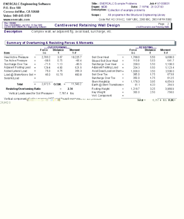
Results Tab - Resisting Moments
This screen presents in tabular form each component contributing to resisting moment, giving weights and lever arms from the front edge of the toe to the centroid of the weight.
Resisting/Overturning ratio is displayed.
For calculating the vertical component, if checked on the OPTIONS screen, and if the EFP method was chosen, the program will back-solve using the Rankine formula to obtain an equivalent internal friction angle.
The force and moment displayed at the bottom accounts for deduction of effect of vertical component, if box on CRITERIA > OPTIONS box has been checked.
Results Tab / Overturning Moments
This screen presents in tabular form each component acting horizontally to overturn the wall/footing system. The centroid of each force is multiplied by its distance up from the bottom of the footing. The Heel Active Pressure includes the effect of surcharges and water table, if applicable, and its Distance is to the centroid of the total lateral force.
The total overturning moment is displayed, and the Resisting/Overturning ratio. The overturning moment is reduced by the toe side active pressure, if this option is selected on the Options screen.
Results & Graphics Tabs
This set of tabs provides the calculated values resulting from your input on the "Data Entry Tabs". Because a recalculation is performed with each data entry, the information on these tabs always reflects the accurate and current results, problem sketch, or stress/deflection diagram.
Results Tab
Soil Pressure @ Toe and Heel
This is the resulting unfactored soil pressure for both the toe and heel. If the eccentricity is outside the middle third, the heel pressure will show 0.00. (Note: when the resultant is outside the middle-third, the program calculates the toe pressure assuming no "tension" at heel).
Allowable Soil Pressure
This is for your reference as input on the Criteria input Screen
Total Bearing Load
This is the sum of all vertical forces.
Resultant Eccentricity
Distance from center of footing to resultant soil pressure.
Eccentricity Within/Outside Middle Third
The resultant is outside the middle third of the footing width if the eccentricity is greater than one-sixth the footing width. (If outside the middle third, the program computes the toe soil pressure assuming no "tension" at heel.)
ACI Factored Soil Pressure @ Toe and Heel
ACI or AASHTO load factors are applied to all dead and live loads to determine total vertical load for soil pressure used in calculating footing moments and shears. This load is then applied at the same eccentricity calculated for service load soil pressures to yield the actual factored soil pressures for footing design using ultimate strength design principles. Note that since only factored vertical loads are applied at the non-factored resultant eccentricity, a true 1.7 load factor applied to lateral earth pressure is not used for footing design. If resultant vertical load eccentricity were to be calculated using factored loads, the distance would not truly represent a correct state of stress in the soil. ACI load factors are intended to give conservative results for stress. Calculation of a factored load eccentricity would give soil pressure diagrams that would not always represent the actual soil pressure distribution under the footing, and yield unreasonable results. Factored lateral earth pressure, however, is always used for concrete stem design.
Mu Design @ Toe/Heel
These are the factored (by 1.4) moments at face of stem for toe and heel moments. Since neither can be greater than the stem base moment (factored if concrete stem), the latter may govern. These moments will be reduced if you choose to neglect the upward soil pressure on the Criteria > Options tab.
A message will indicate which controls.
Shear @ Toe and Heel
The actual shear is calculated from the one-way action in the footing at a distance "d" (footing thickness - rebar cover) from the toe side of the bottom stem section, and at the face of the stem on the heel side. If "d" is greater than the projecting toe or heel length, then the one-way shear is zero.
Allowable Footing Shear
The allowable unit shear equals (0.85 * 2 *![]() ½).
½).
Construction Sketch Tab
This tab provides a sketch of the beam with loads and resulting values shown. Using the [Print Sketch] button will print the sketch in large scale on a single sheet of paper.
Wall Loading DiagramTab
This tab provides a sketch of the wall and it's applied loads. Using the [Print Sketch] button will print the sketch in large scale on a single sheet of paper.
Sample Printout