|
Masonry Lintel |

|

|

|

|

|
|
|
Masonry Lintel |
|
|
|
|

|
Masonry Lintel
|
Masonry Lintel |
|
|
|
|
|
|
|
Masonry Lintel |
|
|
|
|
|
This program provides design analysis for concrete masonry lintels subject to vertical and lateral loads. Lintels can have fixed or pinned ends for most typical conditions, and the user can specify rebar sets within the depth of the lintel.
Vertical loads can be dead and live uniform and concentrated loads. You can have up to four loads of each type, and the uniform loads can be full or partial length.
The program provides analysis for both seismic and wind loads for each recalculation. You can specify seismic factors that apply to the lintel's weight and a wind load.
To allow the program to model different concrete block types, you can specify either lightweight or medium weight block, and additionally enter a lintel weight multiplication factor.
For both the vertical and lateral bending and shear directions, the program calculates allowable bending moments and shear stresses. Also, for both directions, actual moments and shears due to all entered loads are calculated. Final results consist of combined stress ratio calculations for all combinations or dead, live, seismic, and wind vertical and lateral moments and shears.
Basic Usage
| • | Enter Allowable Stresses And Stress Increase Factors. This program allows you to enter the f'm multiplier used to calculate Em, as well as whether special inspection is used or if live loads should be included with seismic or wind loads (we call them Short Term (ST) loads). The seismic factor multiplies the lintel weight and uses the result as the lateral load acting on the lintel (in the same direction as wind load). |
| • | Enter Lintel Data. Clear span is the net opening width the lintel. Depth is the lintel's height, used for vertical bending resistance and weight calculations. Thickness should be entered as NOMINAL thickness. The program extracts wall weight and equivalent solid thickness from internal tables. Using the Fixity entry you can specify whether the lintel has fully fixed end or pinned ends (in both vertical and lateral directions). |
| • | Enter Reinforcing Data. The program works on the concept that you will have pairs of rebars spaced vertically up and down the depth of the lintel. Only the top and bottom sets will be used for vertical bending capacity. Only the bars on one face from each bar set, placed at each face of the lintel, will be used to calculate lateral bending capacity. Please see the example of how the six entries are used correctly. |
| • | Applied Loads allow you to place up to eight dead and live loads on the lintel. When entering Distributed Loads, you can specify a full length load by either leaving both X Left and X Right blank, or setting X-Right equal to the lintel span. |
| • | Review the SUMMARY tab for overstress cases (which will be flagged as No Good). The most important values in this section are the six values listed in the upper right corner under the word combined. |
| • | NOTE! Please be aware that the Load Duration Factor is applied to allowable values, so all stress ratios must be less than 1.0 for a satisfactory design. |
| • | When satisfied, you can Print or Save the data for the current calculation, Reset the calcsheet, or use the Access Menu to choose another program. |
Unique Features
| • | This program calculates all vertical and lateral moments and shears and combines them for all possible stress ratios. This is a very thorough evaluation of combined stresses for seismic and wind design. |
| • | Allowance is made for you to modify the material weight, selectively omit live load from seismic or wind loadings, and models both fix-fix and pin-pin end fixity conditions. |
Assumptions & Limitations
When the lintel's fixity is set to Fixed both vertical and lateral bending are considered fixed.
Example
The data entry for this example is shown in the screen captures that accompany the Data Entry Tabs and Results & Graphics Tabs sections to follow.
Data Entry Tabs
This set of tabs provides entries for all input in this calculation. While you are entering data and switching between these tabs you can view the desired resulting information on the tabs on the right-hand side of the screen (calculated values, sketches, diagrams, etc.). A recalculation is performed after any entry data is changed. After each data entry you can view the results on the right-hand set of tabs.
General Tab
Clear Span
Span length of the lintel used for all bending and shear stress calculations.
Lintel Depth
Total depth (or height) of the lintel.
Thickness
NOMINAL thickness of the lintel.
Fixity
This controls how moments and shears are calculated, by specifying whether the beam is fixed at each end or pinned at each end.
Special Inspection
Enter Y is special inspection will be used during the lintel's construction. A No entry here will reduce all allowable stresses by ½.
Seismic Factor
This value will be applied directly to the lintel weight to generate the lateral seismic load acting on the lintel.
Fs
Allowable steel yield strength. Typically, enter 24,000 for Grade 60 rebar, 20,000 for Grade 40.
f'm
Basic masonry strength, psi.
Em = f' * (entry)
This value will be multiplied by f'm to calculate Em. This value varies between code, and is typically 75 or 1,000.
Weight Multiplier
This multiplier can be used to further factor up or down the unit weight of the lintel. The lintel weight is retrieved from internal tables using your specification of nominal wall thickness and block type. THE LINTEL IS CONSIDERED FULLY GROUTED.
Block Type
This entry controls what block type is being used for determining the wall weight to be recalled from the internal tables. Select Lightweight, Medium Weight, or Normal Weight.
Duration Factor
This factor will be applied to all allowable stress values when short term seismic or wind loads are included in that combination.
Rebar Tab
Rebar Size
Enter the rebar size used for all longitudinal bar sets to be used in the lintel.
# Bars E/F@ Location
Enter the number of rebars at each face of the wall for each bar set. In the example problem, only one #6 was used on each face for all three bar sets.
Clearance @ Top & Bottom
Distance from the top and bottom of the lintel respectively to the center of area of the bar set. These distances will be used as d for vertical bending strength calculations.
# Bar Sets Vertically
Enter the number of bar sets in the lintel.
Spacing Between Bars
This is the clear distance between the bars on each face in a bar set. IT IS ASSUMED THAT THE BARS ARE CENTERED ALONG THE LINTEL VERTICAL CENTERLINE. d used for lateral bending strength calculations is calculated as: Spacing Btwn Bars + (Actual Thickness - Spacing Btwn Bars) / 2
Loads Tab
Wind Load
Wind load applied to the projected surface of the lintel (Span * Depth).
Point Loads & Distance
You may use this entry to apply up to four concentrated dead and live loads to the lintel. Distance refers to the distance from the left end of the lintel to the location of the load.
Distributed Loads
You may use this entry to apply up to four full or partial length uniform dead and live loads to the lintel.
X Left
Distance from the left end of the lintel to the start of the load. Use 0" for full length loads, or partial length loads that begin at the left support.
X Right
Distance from the left end of the lintel to the end of the load. For full length loads, you can enter 0" or the span length here.
Results & Graphics Tabs
This set of tabs provides the calculated values resulting from your input on the "Data Entry Tabs". Because a recalculation is performed with each data entry, the information on these tabs always reflects the accurate and current results, problem sketch, or stress/deflection diagram.
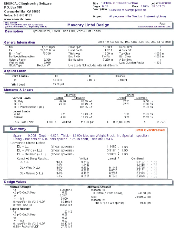
Results / Summary Tab
This area summarizes all the combined stresses, actual moments and shears, and allowable moments and shears. The Combined values for Moment and shear are the ratio of actual/allowable value. The Combined values in the upper right corner combine both lateral and vertical load stress ratios for shear and bending components, and these values should all be less than 1.0" for a satisfactory design. (The Load Duration Factor" was already applied to the allowable stresses).
Results / Moments & Shears Tab
Results / Design Values Tab
Sketch Tab
This tab provides a sketch of the beam with loads and resulting values shown. Using the [Print Sketch] button will print the sketch in large scale on a single sheet of paper.
Printing Tab
This tab allows you to control which areas of the calculation to print. Checking a box will signal that the information described by the item will be printed. However, if there is no information in for a particular selection it will not be printed. So these checkboxes are best described as "If this particular area of the calculations contains data then print it".
Sample Printout