|
Masonry Wall |

|

|

|

|

|
|
|
Masonry Wall |
|
|
|
|

|
Masonry Wall
|
Masonry Wall |
|
|
|
|
|
|
|
Masonry Wall |
|
|
|
|
|
This program provides design and analysis of masonry walls subjected to a combination of axial uniform dead and live loads, eccentric uniform vertical dead and live loads, and lateral loads due to seismic or wind forces. For design of masonry walls using the UBC Slender Wall method, please use the program entitled Slender Masonry Wall Design to perform this type of design.
The user may specify wall and parapet height, added vertical loads, seismic factor or wind load, wall thickness and reinforcing, special inspection, and grout spacing. The program calculates the actual and allowable axial and bending stresses, and combines them using interaction equations for your review.
The working stress method is used to calculate allowable axial and bending stresses. Three load combinations are evaluated for both the top of the wall and mid-height stress analysis using the axial and bending interaction equations.
Basic Usage
| • | Design Data should be entered to define the material strengths, inspection status, and grouting to be used for the wall. Also, the Lateral Load Factor can be used to specify either wind load or seismic factor (please see the specific description in the Detailed Item Summary section). |
| • | The Wall & Load Data section allows you to specify wall heights and additional loads. The wall height can consist of a clear span and parapet extension, both of which will have seismic or wind loads applied. Uniform eccentric and concentric vertical loads can be applied to transfer roof, floor, or upper level loads to the wall. |
| • | Wall Thickness, Rebar Size, Spacing, and Location can be entered and modified during the design process to bring actual stresses below allowable values. |
| • | After entering the above information, calculate the calcsheet and review the Design Summary section. This section gives detailed analysis results for vertical and moment forces, steel and masonry stresses, and combined axial and bending stress results. Both the top of the wall and mid-height are investigated. |
| • | You can also review the Allowable Stresses section to inspect the individual values used to calculate allowable bending and axial stress. The Vertical Loads & Moments section can also be reviewed to see how the dead, live, and lateral loads are combined to achieve the maximum stress results. |
| • | When satisfied, you can Print or Save the data for the current calculation, Reset the calcsheet, or use the Access Menu to choose another program. |
Unique Features
| • | This program permits quick evaluation of a masonry wall subjected to a variety of forces and varying materials and reinforcing. |
| • | Both wind and seismic loads may be applied to the wall. |
| • | The program provides detailed results of various combinations of dead, live, and lateral loads and their effect on moments at the top and mid-height wall sections. |
Assumptions & Limitations
| • | A strip of wall one-foot in length is used for analysis, and all forces should be entered on a force per lineal foot basis. |
| • | P-Delta effects are not considered. The conventional allowable axial stress formula considering slenderness is used. |
| • | provisions for calculating allowable axial stress due to wall slenderness, allowable bending stresses in masonry and concrete, and calculation of actual axial and bending stresses. |
| • | Live load can be specified as floor or roof. If specified as floor, it will always be included with wind/seismic analysis. |
Example
The data entry for this example is shown in the screen captures that accompany the Data Entry Tabs and Results & Graphics Tabs sections to follow.
Data Entry Tabs
This set of tabs provides entries for all input in this calculation. While you are entering data and switching between these tabs you can view the desired resulting information on the tabs on the right-hand side of the screen (calculated values, sketches, diagrams, etc.). A recalculation is performed after any entry data is changed. After each data entry you can view the results on the right-hand set of tabs.
General Tab
Wall Height
The unsupported wall height is measured from the points of lateral support at the floor and roof/second floor. This distance is used to determine moments in the wall due to applied lateral seismic or wind loads.
Parapet Height
This portion of the wall extends above the Clear Span Height and will apply a concentrated moment due to wind or seismic load to the top of the wall. Vertical load due to the parapet weight is also included.
Wall Thickness
Enter the nominal wall thickness you are using or an estimate of what will be needed. A table of "d" values, equivalent solid thickness, and weights are stored in the program, and the appropriate value will be selected based upon nominal wall thickness. Thicknesses allowed are 6", 8", 10", 12", 14", and 16" inches.
Rebar Size
The user enters choice of rebar to be used in the analysis. Rebar area recalled from a typical table. #3 through #11 bars are allowed (#14 and #18 will cause the program to not calculate).
Rebar Spacing
The rebar spacing entered here applies to the rebar size entered above. Please be sure to enter the spacing as it applies to the block modules being used! Only 8", 16", 24", 32", 40", and 48" inches are allowed.
Rebar Location
Select if the vertical reinforcement will be located at the centerline of the wall at the outside edge. NOTE: If reinforcing is stated to be at each face, two layers of rebar will not be used in the evaluation of section properties, only one bar at the d for bar placed at each face will be used.
Depth to Rebar
Enter the depth the program will use from the compression face to the centerline of the rebar.
f'm
Enter the allowable masonry strength to be used in the analysis. The allowable bending and axial stresses calculated from f'm are outlined in a later section. If the user has chosen not to use special inspection, both allowable axial and bending stresses will be multiplied by ½.
Fs
Enter the allowable tension strength of the reinforcing to be used. This value will be used as entered to determine the interaction equations for the design being performed.
Special Inspection
In this location, specify YES if special inspection will be used, allowing full f'm based masonry stresses to be used. Entering NO specifies that no special Inspection will be performed, and all allowable stresses will be reduced by ½.
Solid Grouting
Enter YES if the wall will be solid grouted (regardless of steel spacing). Entering NO specifies that only cells containing vertical reinforcing will be grouted. This input effects the calculation for wall weight and equivalent solid thickness.
Wall Seismic Factor
The seismic factor will be applied to the actual wall weight to generate the lateral load for seismic analysis.
Wall Weight Multiplier
This factor is available for you to modify the wall weight recalled from the internal tables. The value will be applied directly to the internal wall weight and the product displayed as Wall Weight.
Calc of Em = f'm * (value)
In masonry construction the value of Em (Elastic Modulus of the masonry) is calculated as a multiplier applied to f'm. Enter that multiplier here.
Use Grouting at Face Shells Only ?
This item tells the program whether to calculate equivalent solid thickness using just the face cells with grout in the bedding or that all block surfaces that mate with the next block above or below have a grout bed.
Block Type
This entry controls what block type is being used for determining the wall weight to be recalled from the internal tables. Select Lightweight, Medium Weight, or Normal Weight.
Loads Tab
Wind Load
This wind load will be applied to the wall to determine moments for wind load analysis.
Uniform Loads
These uniform loads are vertically applied to the wall at the specified eccentricity. The program resolves this loading to an axial load and concentrated moment applied at the top of the Clear Span Height. The concentrated moment is assumed to decrease to zero at the lower lateral support. This load is included in both bending and axial load computations.
Uniform Load Eccentricity
The user may specify that the uniform dead and live load is applied at an eccentricity. When determining maximum moments, the moment created by the uniform load is always ADDED to the lateral load moments, regardless of whether eccentricity is positive or negative.
Uniform Type
This flag specifies whether the uniform load is due to roof or floor loadings. When floor is used, the uniform live load will be included in wind and seismic analysis combinations.
Concentric Axial Load
The user can specify an axial load applied to the top of the wall, such as load carried down from a floor above or just an added load. This load is considered axial stress only. (No P-Delta moments calculated).
Concentric Load Type
This flag specified whether the axial load is due to roof or floor loadings. When floor is used, the axial live load will be included in wind and seismic analysis combinations.
Results & Graphics Tabs
This set of tabs provides the calculated values resulting from your input on the "Data Entry Tabs". Because a recalculation is performed with each data entry, the information on these tabs always reflects the accurate and current results, problem sketch, or stress/deflection diagram.
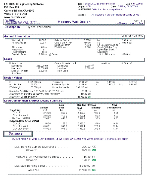
Results / Summary Tab
This section provides a detailed breakdown of the forces and stresses on the wall. Various load combinations are provided at the top and mid-height of the wall to evaluate maximum stresses.
Maximum Values Summary
The area at the top of this tab shows the maximum stress values for the wall, allowable values, and an OK/NG indicator.
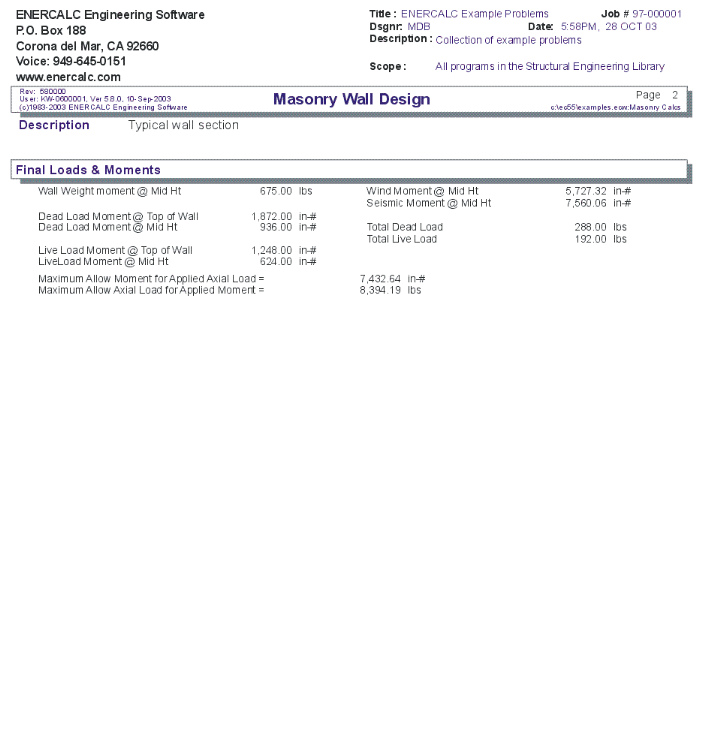
Results / Loads & Moments Tab
This table gives the various moments calculates in the wall, the total dead & live loads, and some back-calculated maximum values for moments and axial loads.
Results / Design Values Tab
Allowable Stresses
In this section the allowable axial, masonry bending, and steel bending stresses are given along with the equations used to create them.
Equiv. Solid Thickness
The equivalent solid thickness of the wall specified, depending on reinforcement spacing and status of solid grouting, is recalled from an internal table of values.
Em
The modulus of elasticity used is calculated as either (1000 -or- 750) * f'm. If special inspection is not used, Em is not reduced by ½.
n - Es / Em
Wall Weight
These include the wall weight from mid height of Clear Height to the top of the Parapet.
As, np, k, j, 2/kj, Radius of Gyration, Moment of Inertia
These are additional design values for your reference.
Sketch Tab
This tab provides a sketch of the beam with loads and resulting values shown. Using the [Print Sketch] button will print the sketch in large scale on a single sheet of paper.
Printing Tab
This tab allows you to control which areas of the calculation to print. Checking a box will signal that the information described by the item will be printed. However, if there is no information in for a particular selection it will not be printed. So these checkboxes are best described as "If this particular area of the calculations contains data then print it".
Sample Printout