|
Multi Span Concrete Beam |

|

|

|

|

|
|
|
Multi Span Concrete Beam |
|
|
|
|

|
Multi Span Concrete Beam
|
Multi Span Concrete Beam |
|
|
|
|
|
|
|
Multi Span Concrete Beam |
|
|
|
|
|
This program provides analysis of simple span or continuous concrete beams. The program allows you to design concrete beams in production line form, letting you rapidly complete many designs simultaneously. The program can handle up to eight spans at once. The end fixities of each can easily be modified to model many types of beams, including (but not limited to):
| • | Simple span beams with cantilevers at one or both ends. |
| • | Single span beams with fixed and/or free ends. |
| • | Continuous beams with up to nine supports. |
| • | Continuous beams with one or both ends pinned, fixed, or cantilevered. |
This flexibility is provided by allowing you to:
| • | Set a flag telling the program to either consider all beams that have pinned ends to be continuous over the support (hooked to the adjacent beam) or consider each span as simply supported. |
| • | For each beam, you can specify fixed, pinned, or free support conditions for each end. This allows you to model any type of span support condition you will encounter (limited to eight spans/nine supports). |
| • | Each span can be loaded with a uniform load, a partial length uniform load, partial length trapezoidal load, up to four point loads, and one concentrated moment. All of these loads can have dead and live components. To further aid your designing ability, you can easily cancel the inclusion of live loads on any span, to perform alternate span load analysis. |
| • | Each span can have top and bottom reinforcing placed at the center and at each end. Shear stirrup spacing is also given for six locations on each span. For each span, the program determines maximum center and support moments, shears, reactions and deflections. |
Basic Usage
| • | Review Scope of Design/Analysis Task. It is essential that you fully understand the use of this program, since its flexibility is the key to your rapid design of multi-span concrete members. Remember that each worksheet column represents a single span between two supports, regardless of the end support conditions. When cantilevers are used, they are considered a span, even though one end is free. |
| • | After you've reviewed the beams you wish to design and how they will be entered using the programs All Spans Continuous and end fixity flags, enter this information in the top section of the worksheet. Remember, when you recalculate the worksheet later to get the results, you can always revise the support fixity data to change any mistakes you might have made. |
| • | You can apply up to three distributed loads to each span. Although three loads total are allowed, the input for each is somewhat different. The UNIFORM item applies dead and live loads to the full span. The FIRST DISTRIBUTED load applies a uniform magnitude dead and live load over all or a portion of the span. The SECOND DISTRIBUTED load allows you to specify a trapezoidal load to any portion of the span. |
| • | Point and moment dead and live loads can be applied anywhere on each span. Loads with negative X-distances, or distances that are longer than the span are ignored. |
| • | Modify beam sizes & reinforcing. To refine your design, type in new beam sizes, and review the stresses and deflections. |
Unique Features
| • | A simple flag can be set on any span to ignore all live loads on that span, making alternate span loading analysis easy. |
| • | Very flexible loadings may be applied to each span, including three uniform/partial/trapezoidal loads. |
Example
The data entry for this example is shown in the screen captures that accompany the Data Entry Tabs and Results & Graphics Tabs sections to follow.
Data Entry Tabs
This set of tabs provides entries for all input in this calculation. While you are entering data and switching between these tabs you can view the desired resulting information on the tabs on the right-hand side of the screen (calculated values, sketches, diagrams, etc.). A recalculation is performed after any entry data is changed. After each data entry you can view the results on the right-hand set of tabs.
General Tab
Operating Mode
This item plays a critical role in governing the calculation procedure for the entire program.
| • | Spans Considered Continuous Over Support : When two beams share the same support , and the support fixity for both beams at that support is Pinned, then the two beams are tied together to form one continuous beam over that support. |
| • | All Spans Considered as Individual Beams : When two beams share the same support , they are always considered as two separate beams and the stresses and rotations in one never affect the other. |
Within each beam span information tab there is a setting for end fixity. Here is how those end fixities are described according to the selection for this item:
When "All Spans Considered as Individual Beams" is chosen:
| • | Free will indicate that the end is completely free of the support and adjacent beam. |
| • | Pinned will affect the beam according to the end fixity of the adjacent beam. If the adjacent beam end is Fixed or Free, then the beam will be pinned and not affected by the adjacent beam. If the adjacent beam is pinned, the two beams are locked together, forming one beam continuous over the support. |
| • | Fixed will attach the beam end to a rigid boundary element, allowing no rotation or vertical movement, and not linked to the adjacent beam. |
When "Spans Considered Continuous Over Support" is chosen :
| • | Free will indicate that the end is completely free of the support, allowing translation and rotation. |
| • | Pinned will allow the beam end to rotate but not translate. |
| • | Fixed will attach the beam end to a rigid boundary element, allowing no rotation or vertical movement. |
Fy
Yield strength of reinforcing steel.
f'c
Compressive strength of concrete.
Stirrup Fy
Yield strength for the stirrup to be designed.
ACI Dead Load Factor
Load factor to be applied to entered dead loads for calculating ultimate moments & shears.
ACI Live Load Factor
Load factor to be applied to entered live loads for calculating ultimate moments & shears.
Typical Span Tab : #1 to #8
Each tab that shows #1 through #8 specifies information for one of the beams of the multi-span beam. Tab #1 is the left-most beam and you work to the right to define additional adjacent spans.
Span Description
Enter a brief description of this span. Leaving it blank is fine.
Span
This equals the span distance of a beam segment.
Beam Depth
Enter the beam depth for this span. Typically this depth will be the same for all spans when designing a beam continuous over several spans.
Beam Width
Enter the beam width for this span. Typically this depth will be the same for all spans when designing a beam continuous over several spans.
Left Fixity, Right Fixity
Specifies how the ends of the beam will be restrained.
Reinforcing
Here you enter the reinforcing area and "d" distance from the TOP OF THE BEAM to the C.G. of the reinforcing. Because of space limitations on this tab you need to enter the reinforcing area. You can use the build-in Rebar Area Calculator by pressing the "Tools & Settings" button at the top of the screen, select "Databases" from the pop-up menu, then select "Rebar". It will display the following window:
Using this window you can create lists of rebar size & quantity, select a range of sizes to list, and sort the resulting list by Area, Quantity, or Bar Size. This will let you easily create bar set designs as you refine your design.
Apply Live Load This Span?
This entry controls whether or not the live load entered for the span will be used or ignored. A YES/NO entry here gives you a simple way to try various live load alternates to determine maximum moments and shears on multi-span beams.
Applied Loads Tab
Uniform
Uniform dead and live load applied to the entire length of the center span. You should be aware that beam weight is not considered in the program, therefore this input should include allowance for beam weight. These values may be positive or negative.
Partial Length Distributed
Uniform dead and live load applied over a full or partial length of the center span. X-Left indicates the distance from the left support to the beginning of the load, and X-Right is the distance from the left support to the right end of the load. These values may be positive or negative.
Trapezoidal Distributed
Uniform or varying dead and live load applied over a full or partial length of the center span. DL/LL @ Left indicates the dead or live load magnitude at the X-Left distance location. DL/LL @ Right indicates the dead or live load magnitude at the X-Right distance location. These values may be positive, negative, or both. X-Left indicates the distance from the left support to the beginning of the load, and X-Right is the distance from the left support to the right end of the load.
Point Load
Concentrated dead and live load applied to the beam.
Moment
Dead and live moment applied to the beam.
Results & Graphics Tabs
This set of tabs provides the calculated values resulting from your input on the "Data Entry Tabs". Because a recalculation is performed with each data entry, the information on these tabs always reflects the accurate and current results, problem sketch, or stress/deflection diagram.
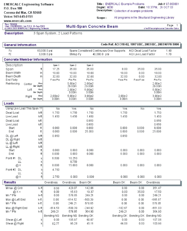
Results Tab
Mu @ Left, Center, & Right
This is the maximum moment calculated between the supports and at the cantilevers. Since only dead and live loads can be applied, this moment represents only ACI load combination 9-1.
Mn * Phi @ Left, Center, & Right
This is the allowable moment capacity of the beam at the left, center, and right end, considering beam size and positive and negative reinforcing, multiplied by 0.9.
The user must determine the extent to which each set of reinforcing bars must extend past the point of maximum moment.
Shear @ Supports
The factored load shears are given for each end of the beam.
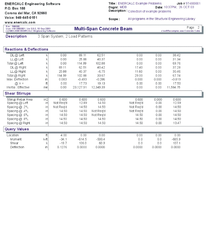
Reactions
The end reactions are calculated using the specified loading, spans, end fixities, and moment distribution results.
Maximum Deflection @ Mid-Span
Using the applied loads, support fixities, and moment distributions results; the resulting deflection curve at 250 points along the beam is searched for the maximum deflection and location. This is the Maximum deflection magnitude, considering both upward and downward displacements. I-effective is determined using ACI equation 9-7 is used.
Effective Stirrup Rebar Area
Enter the area for each stirrup. This area will be used to calculate the required stirrup spacing in the section below. For example, if you are using # 3 stirrups, enter 2 * .11 = 0.22 in2.
Stirrup Spacing List
This area displays the minimum required shear stirrup spacing for six equal length zones along the beam span length. When 999" appears on-screen, that indicates that stirrups are not required.
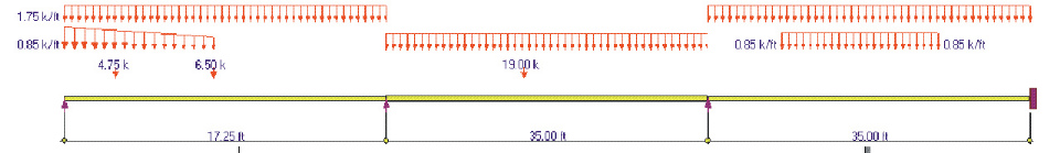
Sketch Tab
This tab provides a sketch of the beam with loads and resulting values shown. Using the [Print Sketch] button will print the sketch in large scale on a single sheet of paper.
Diagrams Tab
This displays a moment, shear, and deflection diagram for the beam with the applied loads and end conditions. Note the two tabs...."Graphic Diagram" and "Data Table". The Data Table tab provides the entire internal analysis at the 1/500th points within the beam.
Printing Tab
This tab allows you to control which areas of the calculation to print. Checking a box will signal that the information described by the item will be printed. However, if there is no information in for a particular selection it will not be printed. So these checkboxes are best described as "If this particular area of the calculations contains data then print it".
Sample Printout