
|
Concrete Beam |

|

|

|

|

|
|
|
Concrete Beam |
|
|
|
|

|
Concrete Beam
|
Concrete Beam |
|
|
|
|
|
|
|
Concrete Beam |
|
|
|
|
|
This program provides design analysis of single span concrete beams with a variety of end restraints, bar placements, and loading conditions.
This program is intended to provide more detailed analysis capability for a single span beam than the Multi-Span program. The Multi-Span program should be used to rapidly design multi-span beams or many simple or cantilevered beams.
Either a rectangular or T type beam can be analyzed by this program. Both types can have reinforcing located at the top and bottom of each end and in the center. All three of these locations can have two layers of top and two layers of bottom reinforcing specified.
The program also supports a variety of end fixities; Fix/Fix, Pin/Pin, Fix/Pin, and Pin/Fix. If cantilevers are needed, you will have to use the Multi-Span beam program. With this variety of reinforcing locations and end fixities, almost any type of concrete beam can be analyzed.
Up to twelve loads can be applied to the beam. These include:
![]() Up to five full or partial length uniform loads with dead, live, and short term components.
Up to five full or partial length uniform loads with dead, live, and short term components.
![]() Up to five point loads with dead, live, and short term components.
Up to five point loads with dead, live, and short term components.
![]() Two applied moments with dead, live, and short term components.
Two applied moments with dead, live, and short term components.
Each recalculation of the program evaluates shears, moments, and deflections for ACI load factor combinations 9-1, 9-2, and 9-3. The concrete section analysis conforms to ACI and UBC codes. This includes the additional load factoring requirements for Seismic Zone 3 and 4, specified in UBC section 2625.
Additional features include; the ability to neglect live loads in combination with short term, optional inclusion of beam weight into applied dead loads, and specification of shear stirrup area ,to create a table of required shear stirrup spacings.
Basic Usage
| • | You must enter the beam span, depth, and width of the beam, however T Flange Thick, Flange Both Sides, and Web Spacing are only used when a Tee type beam is being used. They will be used to determine effective slab width and section properties. Include Bm. Wt is a YES/NO flag that will calculate and add beam weight to the applied dead loads. This is handy when designing large beams with little applied load, as the design size refinements will have the most effect on loading. Stirrup Bar Area indicates the total stirrup area at each stirrup location. This area is used to determine maximum stirrup spacings. |
| • | These items define the material strengths and density, load factoring, and load combinations for the beam. Seismic Zone is used to determine whether applied short term loads are from wind or seismic forces (by entering 0" or non-zero numbers), and also to determine if special load factors for seismic zone 3 and 4 should be used. |
| • | This table provides an easy method to specify reinforcing at any portion of the beam. Center, Left, and Right refer to the location of the reinforcing specified in the two columns below. Each location can have both tension and compression reinforcing by using four available entries to specify rebar depth, size, and quantity. Please note that the d distance (depth) is always measured down from the top of the beam. The column headings Top and Bottom are only for your reference, the actual d distances locate the rebar placement. |
| • | Applied Loads provides entry of point, distributed, and moment loads. The Start and End locations refer to the distance from the left support to the position of start/end of the load. |
Unique Features
| • | All calculations use detailed concrete section analysis routines, which determine exact strain conditions for evaluation of moment capacities. |
| • | This program reduces the typically extensive calculations required for investigation of a doubly reinforced concrete section (with or without T flanges) down to a quick calculation. |
| • | Due to this calculation ability, a section may be quickly designed by a series of WHAT-IF entries for beam size and reinforcing. |
| • | The designer may specify any combination of tension or compression reinforcing. The program will adjust its analysis accordingly. |
Example
The data entry for this example is shown in the screen captures that accompany the Data Entry Tabs and Results & Graphics Tabs sections to follow.
Data Entry Tabs
This set of tabs provides entries for all input in this calculation. While you are entering data and switching between these tabs you can view the desired resulting information on the tabs on the right-hand side of the screen (calculated values, sketches, diagrams, etc.). A recalculation is performed after any entry data is changed. After each data entry you can view the results on the right-hand set of tabs.
General Tab

Beam Span, Depth, &Width
These dimensions specify the beam size and length. The span value will be used to calculate moments, shears, and deflections from the applied loads. Depth and width can be modified to design the beam as required.
Flanged Beam Data
Flange Thickness
This entry specifies the thickness of a T flange at the compression edge of the beam. This entry is optional, and entering zero will mean that a simple rectangular beam is being used. The flange thickness is measured from the top of beam downward (there is no effect on the overall beam depth specified above).
Web Spacing
This item also is only needed when a T type beam is specified, and is used to calculate the effective flange width for the beam, and is the spacing between beams.
Flanges
This item helps the program calculate the effective flange width to be used when a T beam is being used. When the beam is positioned so that the slab extends to either side answer "2 sides".
f'c
Design concrete strength to be used.
Fy
The yield strength of reinforcing to be used.
Concrete Density
This weight is used when the program has been instructed to calculate beam weight.
Seismic Zone
This item specifies whether the short-term loads are due to wind or seismic forces. Entering a 0" indicates that short-term loads are due to wind. Entering 1" to 4" specifies that the short-term loads come from UBC seismic zone loads. Additionally, when zone 3 and 4 is used, the special load factoring for that zone required by the UBC are used.
Does Live Load act with Short Term ?
This entry controls whether or not live loads are used when ACI load combination 9-2 calculations are executed. When short-term loads are due to wind forces, live loads are typically used, whereas seismic forces usually ignore live load effects (except high storage loads).
Include Beam Weight
This YES/NO item tells the program whether to automatically calculate the beam weight and add the dead load to the bending calculations. The weight of the flange is not calculated.
Tee Beam Weight Calculation Method
| • | Use Rectangular Section Only : Calculates the beam weight using only the Beam Width & Beam Depth dimensions |
| • | Use "Tee" section with width = Effective Width : Calculated the beam weight using the width of the "T" section flange equal to the calculated effective width of the flange. |
| • | Use "Tee" section with Width = Web Spacing : Calculated the beam weight using the web spacing of the flange. |
Rebar Tab
This tab allows you to specify the reinforcing to be used in the beam. The location of the rebar 'd' from Top is ALWAYS specified as measured from the top of the beam. The program will internally detect whether the surface where there is tension or compression and will use the rebar properly.

Size & Count
Enter the rebar size # (in 1/8th's of an inch) and quantity for each layer, top and/or bottom, and at the center/ends.
Rebar @ Center of Beam
These entries specify the rebar to be used to resist the maximum moment that will occur between the ends of the beam.
Rebar @ Left and Right End of Beam
These entries specify the rebar to be used to resist the moment at the left end of the beam. If the beam has a "Fixed" end and the tension is in the top of the beam, enter the 'd' distance as just a few inches.
Uniforms Loads Tab
Enter all loads as service loads. Appropriate load factors will be applied internally to calculate ultimate moments & shears (Mu & Vu).

Service Distributed Loads
You can enter up to three distributed loads each with dead, live and short term components that can be either full or partial length.
Service Trapezoidal Loads
You can enter up to two trapezoidal loads each with dead, live and short term components that can be either full or partial length.
Concentrated Loads Tab

ACI Load Factors
This tab specifies the load factors to be used by the program when calculation the factored dead, live, and short term loads to be used in the internal load combinations for determining Mu and Vu for the beam.

Results & Graphics Tabs
This set of tabs provides the calculated values resulting from your input on the "Data Entry Tabs". Because a recalculation is performed with each data entry, the information on these tabs always reflects the accurate and current results, problem sketch, or stress/deflection diagram.
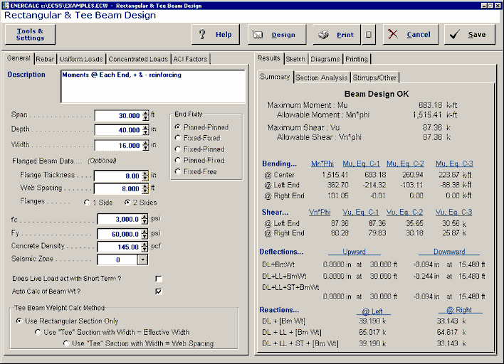
Results / Summary Tab

Maximum Values
Mu
Actual moments due to ACI load combinations 9-1, 9-2, and 9-3 are listed here for the center and end of the beam.
Mn * Phi
Maximum moment capacity at the center and ends of the beam based upon beam size, reinforcing, and material strengths. To determine section capacity, a detailed static analysis of the strain conditions within the beam is executed, with minimum and maximum rebar percentages checked. When compression reinforcing has been specified, the section is still checked for ductile failure (tension steel yield). These moments are multiplied by: Phi = 0.9.
Vu
Actual shear at each end is given here based upon applying ACI load factor combinations 9-1,9-2, and 9-3. Shear is calculated at a distance d from the support.
Vn * Phi
The shear capacity at each end of the member is calculated using the beam dimensions and the minimum shear stirrup spacing calculated for the specified shear stirrup area.
Bending Summary
This area of calculated values gives the allowable moment and factored load moment at each of the three analysis locations. The reference to "C-1", "C-2", and "C-3" are to the ACI factoring load combinations that were run to get the results
Shear Summary
This area of calculated values gives the allowable moment and factored load moment at each of the three analysis locations. The reference to "C-1", "C-2", and "C-3" are to the ACI factoring load combinations that were run to get the results
Deflections
Deflections are listed for two combinations of service loads, which represent static and short-term load combinations. These are instantaneous deflections using ACI equation 9-7. Both upward and downward deflections and the locations at which they occur are given. If any non-zero entry in the Location entry under Additional Deflection Data has been entered, all deflections are listed for that point. Otherwise, 250 span increments are evaluated for maximum and minimum values.
Reactions
Reactions are listed for two combinations of service loads, which represent the static and short-term combinations.
Results / Section Analysis Tab
For the center area, left end and right end all of the critical values developed in the analysis of the concrete section you have specified are given.

Results / Stirrups Tab
This section lists minimum stirrup spacings at seven divisions along the beam length. Shear provisions of ACI section 11.3, 11.4, and 11.5 are evaluated using the Shear Area entered in the section titled Beam Data.

Stirrup Area @ Cross Section
Enter the cross sectional area of the stirrups to be used for the calculation of stirrup spacing. For example, if you are using #3 stirrups there will be two vertical legs capable of resisting shear so the area to enter is 0.11 sq. in * 2 legs = 0.22 in^2.
The table gives the stirrup spacing requirements for various regions of the beam divided up into equal length increments. The maximum stirrup spacing and the actual shear in that area (the maximum) is given.
If the spacing shows as "999" then the shear is below code limits and stirrups are not required for shear (but might be to satisfy minimum reinforcing requirements).
Additional Deflection Values
This section gives additional details of the values calculated in the program for use in calculating section properties and values for deflection
Sketch Tab
This tab provides a sketch of the beam with loads and resulting values shown. Using the [Print Sketch] button will print the sketch in large scale on a single sheet of paper.

Diagrams Tab
This displays a moment, shear, and deflection diagram for the beam with the applied loads and end conditions. Note the two tabs...."Graphic Diagram" and "Data Table". The Data Table tab provides the entire internal analysis at the 1/500th points within the beam.

Printing Tab
This tab allows you to control which areas of the calculation to print. Checking a box will signal that the information described by the item will be printed. However, if there is no information in for a particular selection it will not be printed. So these checkboxes are best described as "If this particular area of the calculations contains data then print it".

Sample Printout

