|
General Timber Beam |

|

|

|

|

|
|
|
General Timber Beam |
|
|
|
|

|
General Timber Beam
|
General Timber Beam |
|
|
|
|
|
|
|
General Timber Beam |
|
|
|
|
|
This program provides design and analysis for wood beams with optional cantilevers at one or both ends. A variety of loads and end fixities can be used to model most span conditions. This program is ideally suited for design and analysis of glued-laminated beams.
This program is provided as an alternative to the Multi-Span program. It gives more detailed analysis capabilities, allows more loads to be applied, gives cambers and bearing stresses, and allows the user to query the program for values at any beam location.
The program divides the beam into 250 span increments and determines maximum shear, moment, deflection, and stress at each location.
You can apply up to seven full and partial length distributed dead and live loads, up to eight point dead and live loads, and up to eight dead and live bending moments. These loads are easily specified by entering the magnitude and location with reference to the left support.
The beam can have either end fixed or pinned in various combinations. From the user defined loading condition, allowable stresses, and end fixities, the program calculates maximum and minimum shears, moments, and deflections.
The user has options to specify automatic calculation of beam weights, reduction of end shears by loads within a distance d from a support, enter unbraced lengths to govern allowable stresses, and set a lamination thickness to be used for automatic member sizing of laminated beams.
Basic Usage
| • | Beam Data defines the size and allowable stress for the beam to be analyzed or designed. Width must always be entered, but Depth can either be entered to analyze a beam or can be automatically selected. |
| • | Lamination Thickness is used by the selection routine as the minimum increment the beam depth should be adjusted to. |
| • | Allowable Stresses will be modified according to load duration factor, size factor, and beam slenderness (as applicable). |
| • | Beam Density is only used when the Use Beam Wt entry is set to YES. |
| • | Design Data modifies the allowable values and modifies how stresses are calculated. Load Duration Factor is applied to all allowable stresses. Use Beam Weight is a YES/NO flag that will automatically add a uniform load to the beam to account for its own weight. Reduce Shear By d is also a YES/NO flag that, when set to Yes, will deduct all loads within a distance Beam Depth from each support when calculating shears. |
| • | End Conditions define how the beam ends are attached to their supports. If cantilever information is entered for a side of the beam that has been specified as fixed, that information (including loads) is ignored. |
| • | This program provides plenty of load capability for loading any part of the beam. All Dist. values position the load with respect to the left support. To apply a load to the left cantilever, enter the distances as negative. |
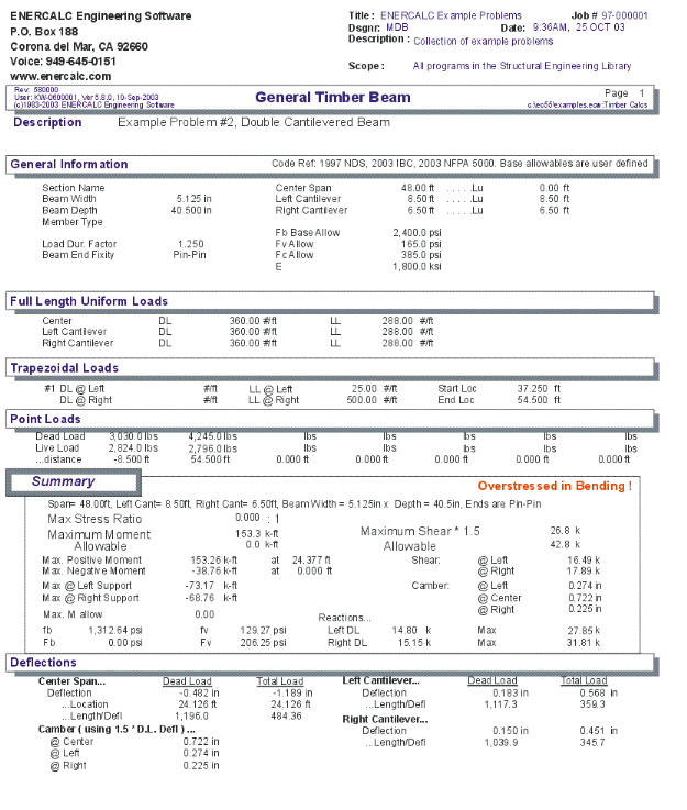
| • | Summary gives stress results for the beam analysis. Maximum Moments are given for the center span and cantilevers (and their locations). Allowable and Actual Stresses are also given for the worst case conditions. Reactions and Deflections are given for dead load only and total load cases. |
| • | Live load is ALWAYS skip loaded to determine the maximum moment in the center span. |
Automatic Beam Sizing
Using the [Design] button you can display a screen that will enable you to set design parameters and examine a database of wood members for selection of those that satisfy your criteria.
| • | Specify maximum deflection ratios for dead and total loads. |
| • | Specify overstress limits for bending and shear forces. |
| • | Use "Go" to start the database search. The beam width and lamination thickness already present in the calcsheet will be used to determine a depth considering bending and shear stresses and deflections. |
Assumptions & Limitations
Live loads are automatically placed in various combinations of center, left, and right cantilever spans to determine maximum moments, shears, deflections, and reactions.
Example
The data entry for this example is shown in the screen captures that accompany the Data Entry Tabs and Results & Graphics Tabs sections to follow.
Data Entry Tabs
This set of tabs provides entries for all input in this calculation. While you are entering data and switching between these tabs you can view the desired resulting information on the tabs on the right-hand side of the screen (calculated values, sketches, diagrams, etc.). A recalculation is performed after any entry data is changed. After each data entry you can view the results on the right-hand set of tabs.
General Tab
This tab provides data entry for all input except loads.
Center Span
Span distance between the left and right supports for the beam.
Left & Right Cantilever
Specifies the length of the cantilevers, if applicable.
Lu : Unbraced Lengths
These lengths define the length of unbraced compression edge ( Le ) for use in calculating allowable bending stresses based on beam slenderness.
For cantilevers, you should always consider whether knee braces or other equivalent means of lateral support are provided to stabilize the compression edge.
End Fixity
This Fixity Code is used to specify the end conditions of your beam.
| • | Pinned-Pinned allows cantilevers at either end, and only rotation of the beam-ends are allowed. |
| • | Fixed-Pinned & Pinned-Fixed allow one end to rotate and have a cantilever, while the other end is rigidly attached to a boundary element (allowing no rotation). If loads are specified with locations past the fixed support, they are ignored. |
| • | Fixed-Fixed attaches both beam ends to rigid boundary elements. All information for cantilevers and load locations outside the center span are ignored. |
[Wood Section] button and entry
Use this button to display the database of wood sections. The database provides selections for sawn, glued-laminated, and manufactured lumber. Please refer to the previous chapter describing using database in the Structural Engineering Library. Pressing [Wood Section] will display the following selection window:
Depth & Width
Enter the beam width & depth you wish to use, or select the beam from the database (see above).
Beam Type
This selection controls how the Size of Volume factor is calculated. If "Sawn" is selection "Cf" is calculated. If "GluLam" is selected then "Cv" is calculated. If "Manufactured or So. Pine" selected then NO factor (Cf or Cv) is calculated.
Wood Species : [Stress] button & entry
This allows you to use the built-in NDS & Manufactured lumber allowable stress database to retrieve allowable stresses. When you press the button you will see this selection window. Please see the section earlier in this User's Manual that give information and usage for the databases.
Fb-Bending : Base Allowable
Basic allowable bending stress to be used for design and analysis. This stress will be modified based by slenderness, size factor, and load duration factor.
Fv-Shear
Allowable shear stress to be used in design. This allowable will be modified by the load duration factor.
Fc-Bearing
Allowable bearing stress perpendicular to the grain.
Elastic Modulus
Enter the modulus of elasticity to be used in determining deflections and calculation of F'b for laterally unbraced beams.
Repetitive Member Flag
Check this box if the multi-span beam can be considered to be a repetitive member according to NDS definitions.
Load Duration Factor
Load duration factor to be applied to allowable bending and shear stresses. Application of this factor is in accordance with NDS.
Lamination Thickness
You can specify a lamination thickness to be used to determine the minimum required depth increment. The program determines the minimum number of laminations of this thickness that are needed, and rounds up a full lamination. Leave this value set to zero for exact depth calculations.
Calc Shear at "depth" from Support ?
This YES/NO flag allows you to disable the automatic subtraction of all loads within a distance Beam Depth from a support (when determining design shears).
Uniform & Trapezoidal Loads Tab
Uniform Loads Over Full Span
Auto Calc Beam Weight
Check this box to have the program calculate the beam weight and apply it as a uniform loads on the center and cantilever spans.
Wood Density
Enter the density of the beam. It will only be used if the Auto Calc Beam Weight box is checked.
Center Span Dead & Live Loads
Enter the uniform dead and live loads acting on the center span of the beam. These entries allow you to apply one uniform dead and live load
to the center span.
Left & Right Cantilever Dead & Live Loads
Enter the uniform dead and live loads acting on either of the cantilevers. The loads are applied to the entire cantilever length.
Trapezoidal Loads
This section allows you to enter loads that can have different end magnitudes and can start and end at any location along the beam.
--->>> Note! Entering ONLY the "Left" value and leaving the "Right" load and BOTH Start and End location blank will make the load a uniform full length loads.
Load @ Left & Right
These entries define the magnitudes of the ends of the loads. The load magnitude is then linearly interpolated between the starting and
ending points. These values may be positive or negative to indicate downward or upward force direction.
Left & Right Locations
The starting and ending extents of the loads are entered here. These values are entered as the distance from the LEFT support. For loads on
the left cantilever enter a negative value. For loads on the right cantilever the location must be greater than the "Center Span" length.
Point & Moment Loads Tab
Point Loads
Dead & Live Loads
This entry allows you to apply up to eight concentrated dead and live loads to any portion of the entire beam; center span or cantilevers.
Distance
All distances are referenced from the left support.
Moment Loads
Dead & Live Moment
This entry allows you to apply up to eight moments dead and live loads to any portion of the entire beam.....center span or cantilevers.
Distance
All distances are referenced from the left support.
Results & Graphics Tabs
This set of tabs provides the calculated values resulting from your input on the "Data Entry Tabs". Because a recalculation is performed with each data entry, the information on these tabs always reflects the accurate and current results, problem sketch, or stress/deflection diagram.
Summary / Results Tab
Max. Stress Ratio
Considering all placement options for live loads and examining the maximum moment at all locations of the beam, this is the maximum stress ratio calculated by dividing that moment by the beam's Sxx section modulus times the allowable bending stress.
Maximum Moment & Stress
This is the maximum moment used in the "Max. Stress Ratio" calculation and the resulting stress in the beam. Also given is the allowable moment and stress.
Maximum Shear * 1.5
Considering all placement options for live loads and examining the maximum shear at all locations of the beam, this is the maximum value multiplied by the code required 1.5 to arrive at a design shear. Also given are the actual and allowable stresses
Max Mid-Span Deflection
Considering all placement options for live loads and examining the maximum deflection across the center span of the beam, this the maximum value. Also given is the Length / Deflection ratio
Moment Details
More details about the maximum values for positive and negative moments and support moments are given.
Shears
This is the maximum shear calculated at both ends. Live load is automatically placed in all possible location combinations to determine the maximum shear value on each side of the supports. (This shear is not modified for loads within d distance from end of beam nor multiplied by typical 1.5 shear factor. Please see Design Shear for those adjusted numbers).
Reactions
For both left and right support, the dead and total load reactions are given. When cantilevers are present, live load is omitted from the cantilever at the opposite end from the support. Live load is automatically placed in all possible location combinations to determine the maximum shear value on each side of the supports.
Summary / Stress Calcs Tab
Bending Analysis
Le
Unbraced length used for allowable bending stress calculation of "CL" factor.
Cv
This item will display as "Cv" for glued laminated beams when the volume factor applies and as "Cf" for sawn or manufactured members when the size factor applies.
Rb
Slenderness ratio for the beam.
CL
Reduction factor that will be applied to the Fb: Basic Allowable to reduce the allowable bending stress based on unbraced compression edge lengths.
Sxx & Area
Section properties for the beam being analyzed.
Max. Moment, Sxx Required, Fb:Allowable @ Span
This is a summary of important bending analysis values at the three critical locations in the beam.
Shear Analysis
Design Shear
By dividing the entire beam into 250 increments, the maximum shears are determined by applying live loads on various portions of the beam to create maximum effects on either side of the supports and mid-span. Then all loads within a distance equal to the beam depth from the end of beam are subtracted, and the result multiplied by 1.5.
Area Required
Required shear area of beam calculated by Design Shear / FV:Allowable.
Fv:Allowable
Fv is equal to the allowable shear stress times load duration factor.
Bearing @ Supports
Maximum reactions at each support are divided by allowable bearing stress, and beam width to determine the required length of bearing.
Summary / Deflections Tab
Dead Load & Total Load Values
Dead load deflections represent the calculated deflections when the entered dead load (and beam self weight if chosen) is applied to the entire span.
Total load deflections represent the MAXIMUM deflections at each location on the beam.
Deflection, Location & Length/Defl Ratio
This area gives the deflection value, the location from the LEFT support (negative for left cantilever), and Span Length / Deflection Ration.
Note: negative deflections are downward
Note: For cantilevers the deflection ratio is calculated as (2.0 * Cant. Length) / (Deflection at end). Because code deflection ratio limits are suggested for simple span beams with two supports a cantilever represents just 1/2 of the equivalent span.
Camber
This is 1.5 times the dead load deflections
Summary / Query Tab
Locations
Enter the location measures from the left support for where you would like the detailed value calculated.
Use "LL" at xxxxxx for Query
This selection instructs the program how to apply the live load for this query value.
Calculated Values
Gives the calculated moment, shear, and deflection for the location specified.
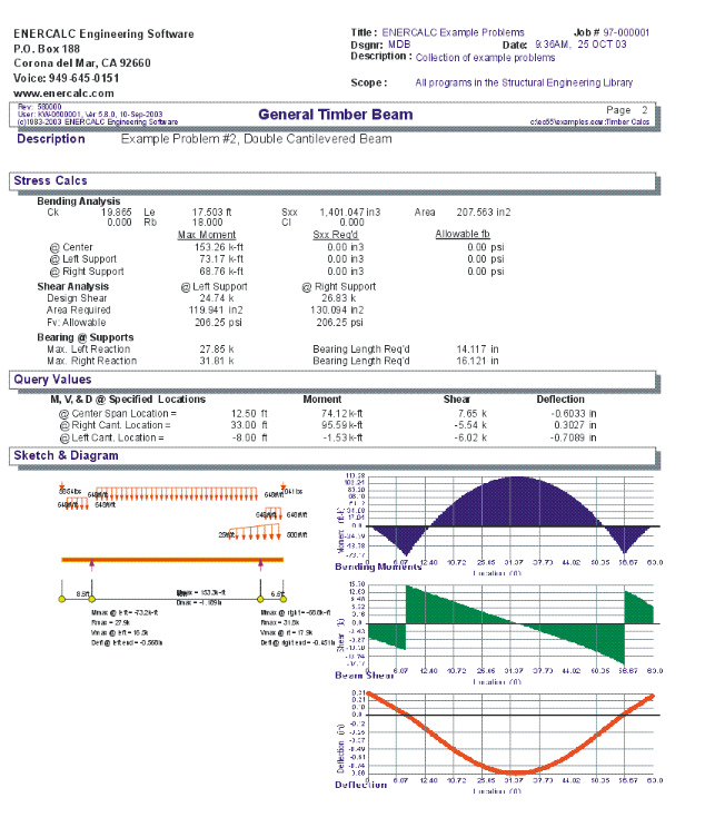
Sketch Tab
This tab provides a sketch of the beam with loads and resulting values shown. Using the [Print Sketch] button will print the sketch in large scale on a single sheet of paper.
Diagrams Tab
This displays a moment, shear, and deflection diagram for the beam with the applied loads and end conditions. Note the two tabs...."Graphic Diagram" and "Data Table". The Data Table tab provides the entire internal analysis at the 1/500th points within the beam.
Printing Tab
This tab allows you to control which areas of the calculation to print. Checking a box will signal that the information described by the item will be printed. However, if there is no information in for a particular selection it will not be printed. So these checkboxes are best described as "If this particular area of the calculations contains data then print it".
Notes Tab
This tab contains some general notes about the usage of the results of this program.
Sample Printout
Page 1
Page 2