|
Multi Span Timber Beam |

|

|

|

|

|
|
|
Multi Span Timber Beam |
|
|
|
|

|
Multi Span Timber Beam
|
Multi Span Timber Beam |
|
|
|
|
|
|
|
Multi Span Timber Beam |
|
|
|
|
|
This program provides design and analysis of simple span or continuous timber beams. This compact program can let you design wood beams in production line form, letting you rapidly complete many designs simultaneously. The program can handle up to eight spans at once. The end fixities of each can easily be modified to model many types of beams, including (but not limited to):
| • | Simple span beams with cantilevers at one or both ends. |
| • | Single span beams with fixed and/or free ends. |
| • | Continuous beams with up to nine supports. |
| • | Continuous beams with one or both ends fixed or cantilevered. |
| • | This flexibility is provided using a Yes/No prompt All Spans Simple Support. |
| • | Answering NO tells the program that beams that have pinned ends at the same support are connected and continuous over that support. |
| • | Answering YES tells the program that each data entry column represents a single beam that is unaffected by the beam on either side of it. |
Each span can be loaded with dead and live uniform, a partial length uniform, partial length trapezoidal, and concentrated loads. To further aid your design, you can easily omit live load on any span to perform alternate span load analysis
Unique Features
| • | Full NDS code checks are made considering length effects on allowable bending stresses. |
| • | A simple flag can be set on any span to ignore all live loads on that span, making alternate span loading analysis easy. |
| • | Very flexible loadings may be applied to each span, including three uniform/partial/ trapezoidal loads. |
| • | The program can perform automatic member depth selection using stress and deflection criteria. All that is required is for you to specify the allowable stresses and desired beam width. |
Assumptions And Limitations
User must enter ACTUAL (not nominal) beam width and depth for analysis. The program calculates the required depth, and the user can then enter the beam depth to be used for an exact analysis of stresses.
The following span condition is not permitted:
Automatic Member Design
This program automatically selects member depth requirements for single or multiple span beams. By pressing Design you will access the design window. This screen allows you to:
| • | Specify dead, live, and dead+live load Span/Deflection ratio limits. |
| • | Specify overstress limits for bending and shear forces. |
| • | Specify a minimum dimension to increment beam depths when determining a required depth. |
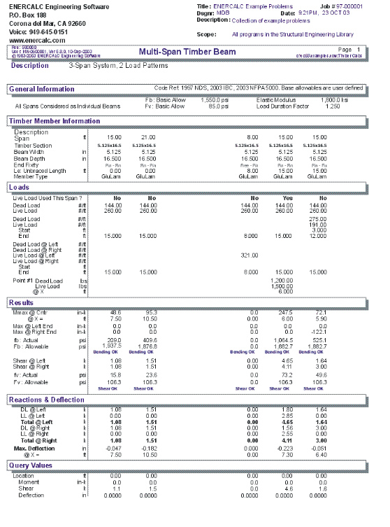
Example
The data entry for this example is shown in the screen captures that accompany the Data Entry Tabs and Results & Graphics Tabs sections to follow.
Data Entry Tabs
This set of tabs provides entries for all input in this calculation. While you are entering data and switching between these tabs you can view the desired resulting information on the tabs on the right-hand side of the screen (calculated values, sketches, diagrams, etc.). A recalculation is performed after any entry data is changed. After each data entry you can view the results on the right-hand set of tabs.
General Tab
This tab contains entries for values that will be used for ALL the beams in the multi-span system.
Operating Mode
This item plays a critical role in governing the calculation procedure for the entire program.
| • | Spans Considered Continuous Over Support : When two beams share the same support , and the support fixity for both beams at that support is Pinned, then the two beams are tied together to form one continuous beam over that support. |
| • | All Spans Considered as Individual Beams : When two beams share the same support , they are always considered as two separate beams and the stresses and rotations in one never affect the other. |
Within each beam span information tab there is a setting for end fixity. Here is how those end fixities are described according to the selection for this item:
When "All Spans Considered as Individual Beams" is chosen:
| • | Free will indicate that the end is completely free of the support and adjacent beam. |
| • | Pinned will affect the beam according to the end fixity of the adjacent beam. If the adjacent beam end is Fixed or Free, then the beam will be pinned and not affected by the adjacent beam. If the adjacent beam is pinned, the two beams are locked together, forming one beam continuous over the support. |
| • | Fixed will attach the beam end to a rigid boundary element, allowing no rotation or vertical movement, and not linked to the adjacent beam. |
When "Spans Considered Continuous Over Support" is chosen :
| • | Free will indicate that the end is completely free of the support, allowing translation and rotation. |
| • | Pinned will allow the beam end to rotate but not translate. |
| • | Fixed will attach the beam end to a rigid boundary element, allowing no rotation or vertical movement. |
[Stress] button & entry
This allows you to use the built-in NDS & Manufactured lumber allowable stress database to retrieve allowable stresses. When you press the button you will see this selection window. Please see the section earlier in this User's Manual that give information and usage for the databases.
Fb-Basic Allow.
Enter allowable bending stress. This value will be multiplied by LDF , Cf, and reduced per unbraced length (as applicable) to determine Fb-Modified Allowable.
Fv-Basic Allow.
Enter the basic allowable shear stress. This value will be multiplied by LDF to get Fv-Allowable.
E
Enter the elastic modulus for the beam being investigated.
Load Duration Factor
Load duration factor for each span will be applied to the final allowable stresses (as applicable per code considering beam slenderness). This factor will be applied to the allowable bending and shear stresses to increase/decrease the beam's capacity based upon the nature of the applied load.
Repetitive Member Flag
Check this box if the multi-span beam can be considered to be a repetitive member according to NDS definitions.
Typical Span Tab : #1 to #8
Each tab that shows #1 through #8 specifies information for one of the beams of the multi-span beam. Tab #1 is the left-most beam and you work to the right to define additional adjacent spans.
Span Description
Enter a brief description of this span. Leaving it blank is fine.
Span
This equals the span distance of a beam segment.
Le:Unbraced Length
If the span will have the compression edge laterally unbraced for some distance, enter the distance here. This length will be used to determine whether the beam falls into the short, intermediate, or long beam classification for determination of allowable bending stress.
For continuous beams, remember that the true meaning of this value is distance between points of contra flexure, and most likely will NOT be the distance between supports.
This entry is the unsupported compression edge length, corrected for span type per AITC/UBC code. Use the following table as a guide.
Type of Beam Span and Nature of Load Value of Effective Length, Le
Single Span beam, load concentrated at center 1.61 Lu
Single Span beam, uniformly distributed load 1.92 Lu
Single Span beam, equal end moments 1.84 Lu
Cantilever beam, point load at unsupported end 1.69 Lu
Cantilever beam, uniform load w/ point load at end 1.69 Lu
Single Span beam, any other load 1.92 Lu
Left Fixity, Right Fixity
Specifies how the ends of the beam will be restrained.
[Wood Section] button and entry
Use this button to display the database of wood sections. The database provides selections for sawn, glued-laminated, and manufactured lumber. Please refer to the previous chapter describing using database in the Structural Engineering Library. Pressing [Wood Section] will display the following selection window:
Beam Width
Beam width is defined by the user, and will be used to determine section properties for stresses and deflections. This value can be modified at any time during the analysis process. The width is also used as the basis for the Selection procedure to determine required beam depth. The width must be ACTUAL (not nominal) width.
Beam Depth
Enter the actual depth of the beam, which in turn will be used to determine depth factor (Cf), actual bending stress, shear stress, and deflections. This value can be modified at any time to refine your designs. You can also leave this entry zero, and press [F7] to display the selection window. From there the program automatically designs the depth of the member.
Beam Type
This selection controls how the Size of Volume factor is calculated. If "Sawn" is selection "Cf" is calculated. If "GluLam" is selected then "Cv" is calculated. If "Manufactured or So. Pine" selected then NO factor (Cf or Cv) is calculated.
Apply Live Load This Span?
This entry controls whether or not the live load entered for the span will be used or ignored. A YES/NO entry here gives you a simple way to try various live load alternates to determine maximum moments and shears on multi-span beams.
Applied Loads
Uniform
Uniform dead and live load applied to the entire length of the center span. You should be aware that beam weight is not considered in the program, therefore this input should include allowance for beam weight. These values may be positive or negative.
Partial Length Distributed
Uniform dead and live load applied over a full or partial length of the center span. X-Left indicates the distance from the left support to the beginning of the load, and X-Right is the distance from the left support to the right end of the load. These values may be positive or negative.
Trapezoidal Distributed
Uniform or varying dead and live load applied over a full or partial length of the center span. DL/LL @ Left indicates the dead or live load magnitude at the X-Left distance location. DL/LL @ Right indicates the dead or live load magnitude at the X-Right distance location. These values may be positive, negative, or both. X-Left indicates the distance from the left support to the beginning of the load, and X-Right is the distance from the left support to the right end of the load.
Point Load
Concentrated dead and live load applied to the beam.
Moment
Dead and live moment applied to the beam.
Results & Graphics Tabs
This set of tabs provides the calculated values resulting from your input on the "Data Entry Tabs". Because a recalculation is performed with each data entry, the information on these tabs always reflects the accurate and current results, problem sketch, or stress/deflection diagram.
Results Tab
This tab gives ALL the calculated values for the span tab selected.
Moments & Stresses
These are the maximum values to use for design for this span. The "Mid-Span" moment can occur anywhere between the two end supports. It is possible that this number is right next to the support.
Max. Moment @ Mid-Span
To determine maximum moments, the following technique is used:
| • | Fixed end moments are calculated for each span. When LL Flag is set to NO, no live loads are applied to that span. |
| • | A 16 pass moment distribution is performed on the entire eight span system. |
| • | The resulting end moments are then applied to each beam end and the resulting moments, shears, and deflections for the span are calculated. Each beam is divided into 250 increments for this process. |
Max @ Left End & Right End
Maximum values for the calculated moments at the ends (or over the supports when a cantilever is present).
Bending Stress : Actual & Allowable
Allowable bending stress calculated considering Cf, load duration factor, and from the evaluation of allowable bending stress, due to the unbraced length. Actual bending stress is the maximum of positive or negative moment, divided by section modulus of the beam at that span location. Continuous beams will have this value equal to the maximum stress between the supports.
Shear Stress
Allowable stress is calculated load duration factor applied to Fv (see below). Actual shear stress is the maximum unit shear stress at the end of the beam. To determine net shear at the beam end, all loads within a distance d away from the end of the member are subtracted from the end shear. This value is multiplied by 1.5 and divided by beam width times beam depth. When the beam is continuous over a support, shear on BOTH SIDES of the support is evaluated.
Max. Deflection
Using the applied loads, support fixities, and moment distribution results, the resulting deflection curve at 250 points along the beam is searched for the maximum deflection and location. This is the maximum deflection, considering both upward and downward displacements. Negative sign is downward deflection.
Shear @ Left & Right Supports
The calculates shears at each support are given. This value is the maximum shear after checking both sides of the support.
Reactions @ Left & Right Supports
Reactions are calculated using dead load and the live load as selected to be applied for each span.
Query Values
In this area you can enter a distance location along the span, measured from the left support, ad have the shear, moment, and deflection at that location calculated.
Cf or Cv
This item displays the size factor "Cf" for sawn members or the volume factor "Cv" for glued-laminated members.
Rb
This value is calculated from the compression edge slenderness of the beam and applied as a factor to the allowable stress.
Le
This is the effective length used in the calculation of Rb.
Sketch Tab
This tab provides a sketch of the beam with loads and resulting values shown. Using the [Print Sketch] button will print the sketch in large scale on a single sheet of paper.
Diagrams Tab
This displays a moment, shear, and deflection diagram for the beam with the applied loads and end conditions. Note the two tabs...."Graphic Diagram" and "Data Table". The Data Table tab provides the entire internal analysis at the 1/500th points within the beam.
Printing Tab
This tab allows you to control which areas of the calculation to print. Checking a box will signal that the information described by the item will be printed. However, if there is no information in for a particular selection it will not be printed. So these checkboxes are best described as "If this particular area of the calculations contains data then print it".
Sample Printout