|
Timber Ledger |

|

|

|

|

|
|
|
Timber Ledger |
|
|
|
|

|
Timber Ledger
|
Timber Ledger |
|
|
|
|
|
|
|
Timber Ledger |
|
|
|
|
|
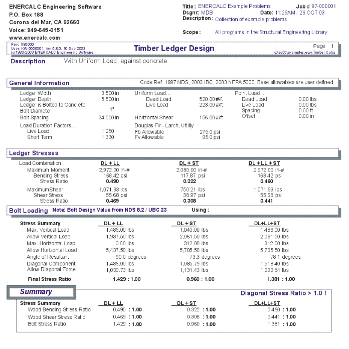
This program provides design analysis for wood ledgers carrying vertical and lateral loads. It is intended for buildings where ledgers are bolted to concrete or masonry walls, and transfer all loads to the wall via single shear in the bolts.
Vertical uniform dead and live loads, vertical concentrated dead and live loads, and horizontal shear can be applied to the ledger. Vertical loads are used to calculate maximum moments and shears considering that the ledger is a continuous beam over the bolted supports.
For the concentrated loads, you enter the distance from a bolt, and the load spacing. The program will then calculate the number of loads that are applied to the ledger between bolts, combine that moment diagram with the uniform loads, and calculate maximum moments and vertical reactions at the bolts.
The vertical and horizontal loads are combined to give a resultant maximum force and application angle. The Hankinson formula is then applied to determine the maximum allowable force at that angle.
You may enter live load and short term load duration factors, ledger width and depth, bolt diameters, and whether the ledger is bolted to concrete or masonry (for use of UBC allowable increases to bolt shear values). Both ledger and bolts are checked for combination of DL+LL, DL+ST (short term), and DL+LL+ST.
Basic Usage
| • | Determine Dead and Live Loads. Since the program assumes repeating concentrated loads, you can enter the vertical loads as either uniform or a single concentrated load at a specified spacing. |
| • | Horizontal Shear is entered as lbs/foot and is multiplied by the bolt spacing to get the tributary load per bolt. When you have combined drag strut and unit shears acting on the ledger, be sure to resolve them to a lbs/foot value. |
| • | Enter Ledger Depth, Width, and Allowable Stresses. You must enter the exact member size (not nominal). You can use the timber database to get these values. |
| • | The Against Concrete entry is used to determine whether the UBC modification to allowable bolt values should be used for single shear against concrete. |
| • | Enter Bolt Size and Spacing. The program supports ½" -> 1" bolts, and will adjust the allowable values for the nearest size category. |
Assumptions & Limitations
When calculating moments due to point loads, the program does not check an infinite number of location combinations when the point load spacing is an uneven multiple of the bolt spacing. It will, however, check if the Offset distance is greater than the Bolt Spacing, and move the load over to a new offset equal to Bolt Spacing - Offset
Example
The data entry for this example is shown in the screen captures that accompany the Data Entry Tabs and Results & Graphics Tabs sections to follow.
Data Entry Tabs
This set of tabs provides entries for all input in this calculation. While you are entering data and switching between these tabs you can view the desired resulting information on the tabs on the right-hand side of the screen (calculated values, sketches, diagrams, etc.). A recalculation is performed after any entry data is changed. After each data entry you can view the results on the right-hand set of tabs.
General Tab
Ledger Width & Depth
Exact sizes of ledger.
Bolt Diameter & Spacing
Enter the bolt diameter and spacing you wish to use. You can quickly change these values and recalculate to arrive at a satisfactory design.
Attached to Concrete ?
Enable this checkbox when the ledger is bolted to a concrete or masonry wall. This changes the way bolt values are pulled from UBC table 25-F. When the ledger is against concrete, the double shear values for a member ½ the width are used.
Building Code Used
Select the building code you are using. This controls the allowable bolt values to be used. If "1991 & earlier UBC" is chosen then 1994 UBC Table 23-I-F allowable bolt values are used. If "1994 & Later UBC and NDS" is chosen then the bolt design value are from NDS 8.2 / UBC 2336.2.
[Stress] button & entry
This allows you to use the built-in NDS & Manufactured lumber allowable stress database to retrieve allowable stresses. When you press the button you will see this selection window. Please see the section earlier in this User's Manual that give information and usage for the databases.
Fb & Fv Allowable
Basic allowable bending & shear stresses. These values will be increased by the Live Load and Short Term Load Duration factors when calculating allowable stresses for the three load combinations.
Live Load Stress Increase
This is a factor that will be applied to the allowable bending and shear stresses for calculation of final allowable values when live load is used within the three different load combinations.
Short Term Stress Increase
This is a factor that will be applied to the allowable bending and shear stresses for calculation of final allowable values when the horizontal shear load is used within the second two load combinations.
Ledger Load Tab
NOTE! This program assumes the segment of ledger that you are designing behaves as a continuous beam, with negative moments over the bolts transferring to adjacent ledger sections. The point loads you enter will be used as is, so if your point load spacing is different from the ledger bolt spacing, enter the bolt offset such that the greatest moment will be generated using the continuous span assumption.
Uniform Load
Enter the uniform dead and live load applied to the ledger.
Point Load & Spacing
Enter the concentrated dead and live load that will be applied to the ledger at a typical spacing. This entry is intended for you to enter repeating loads from framing members.
Point Load Offset
This is the distance of the first point load from a ledger anchor bolt. The point loads will be automatically repeated in calculations from this point onward using the Point Load Spacing value.
Horizontal Shear
This is the shear applied to the ledger along its longitudinal axis. Be sure to adjust combined drag load and unit shears to a proper value.
Results & Graphics Tabs
This set of tabs provides the calculated values resulting from your input on the "Data Entry Tabs". Because a recalculation is performed with each data entry, the information on these tabs always reflects the accurate and current results, problem sketch, or stress/deflection diagram.
Results Tab
Load Combination Columns
Each of the three columns represents different combinations of the dead, live, and lateral loads.
Maximum Moment
This is the maximum moment in the ledger, analyzed as a continuous beam, considering uniform and point loads.
Maximum Moment & Stress Ratio
Actual bending stress for the ledger using the Maximum Moment. Actual bending stress divided by allowable stress (after it is modified by the appropriate load duration factor).
Maximum Shear & Stress Ratio
Maximum shear stresses at the bolts considering vertical loads and a continuous span beam.
Stress Summary
Maximum Vertical Load
Using the applied uniform dead and live loads and point loads, the maximum vertical bolt reaction is calculated.
Allowable Vertical Load
Allowable bolt shear value perpendicular to grain in wood members, adjusted by the load duration factors.
Maximum Horizontal Load
This is simply the applied horizontal shear * bolt spacing.
Allowable Horizontal Load
Load Allowable bolt shear value perpendicular to grain in wood members, adjusted by the load duration factors.
Diagonal Component
Using a square root sum of the squares combination of the maximum vertical and horizontal loads to the bolts, the resultant force is calculated.
Angle of Resultant
Angle of application of the Diagonal Component.
Hankinson Allowable
Using the Resultant Angle and allowable parallel and perpendicular to grain stress values, the final allowable force is calculated, to be compared with the Diagonal
Sketch Tab
This tab provides a sketch of the beam with loads and resulting values shown. Using the [Print Sketch] button will print the sketch in large scale on a single sheet of paper.
Sample Printout