|
Flush Wall Pilaster |

|

|

|

|

|
|
|
Flush Wall Pilaster |
|
|
|
|

|
Flush Wall Pilaster
|
Flush Wall Pilaster |
|
|
|
|
|
|
|
Flush Wall Pilaster |
|
|
|
|
|
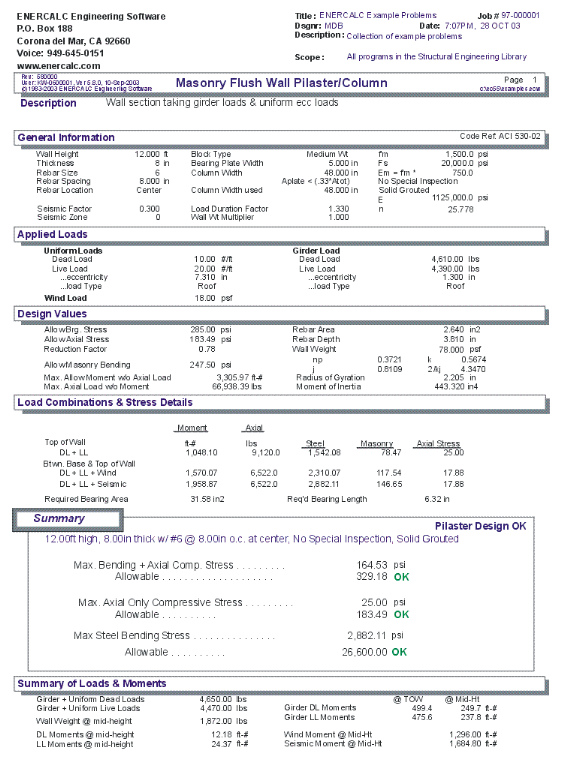
This program provides design and analysis of columns contained entirely within the thickness of a masonry wall. The column may be subjected to a combination of eccentric vertical loads and lateral loads due to seismic or wind forces.
Loading conditions include a dead and live girder load applied to a bearing seat, dead and live uniform load applied eccentrically to the top of the wall, and lateral loads due to wind and seismic forces.
The user may specify allowable masonry and steel stresses, status of special inspection, status of solid grouting, seismic factor, wind load, and bearing plate dimensions, wall thickness, rebar size and spacing, rebar location, and wall span data.
All axial load and bending moment stresses are calculated and combined using the interaction equation. Combined stresses at the top of the pilaster and at mid-height are checked.
Basic Usage
| • | In the section titled Design Data, enter the material strengths and inspection status for the wall. Seismic Factor and Wind Load are both used to generate lateral loads applied to the wall. The resulting moments are detailed in the Summary section. You must also enter a Bearing Plate Length to be used to spread the applied vertical load out over an effective width of the pilaster. |
| • | The Loading Data section allows you to apply eccentric vertical uniform roof or floor loads and a concentrated girder load. You can use either or both of these entries to apply vertical load to the pilaster. |
| • | Pilaster Data defines the clear span, thickness, and reinforcing for the flush wall pilaster. You typically modify these three values while recalculating to reach the final pilaster design. You can place the rebar at the Center or Edge of the wall. |
| • | The above entries are all that is required to completely specify a wall section. Calculating the program will perform the analysis for maximum bending and axial stresses. The analysis always produces results for both wind and seismic load cases. |
| • | You can then proceed to Check Actual And Allowable Moments, deflection ratios, reinforcing percentages, and axial stress levels. If any are not within limits, you can modify reinforcing or wall thickness to bring the actual values into compliance. |
| • | When finished, Print or Save the data for the current calculation, Reset all the program values to zero for a new problem, or use the Access Menu to use another program. |
Unique Features
| • | This program permits quick evaluation of a flush wall pilaster subjected to a variety of forces, with varying materials and reinforcing. |
| • | Both seismic and wind analysis is provided. |
| • | Detailed bending and axial stress results are supplied for various load combinations at the top of the column and mid-height. |
Assumptions & Limitations
| • | P-Delta effects are not considered. The conventional formulas for evaluating allowable axial and bending stresses in masonry are used, based on the U.B.C. and similar codes. |
| • | Girder loads and uniform vertical loads are both applied to the pilaster at the same elevation. |
Example
The data entry for this example is shown in the screen captures that accompany the Data Entry Tabs and Results & Graphics Tabs sections to follow.
Data Entry Tabs
This set of tabs provides entries for all input in this calculation. While you are entering data and switching between these tabs you can view the desired resulting information on the tabs on the right-hand side of the screen (calculated values, sketches, diagrams, etc.). A recalculation is performed after any entry data is changed. After each data entry you can view the results on the right-hand set of tabs.
General Tab
Pilaster Height
The effective height is measured from the points of lateral support at the floor and roof/second floor. This distance is used to determine moments in the wall due to applied lateral seismic and wind loads. For flush-wall columns in walls with no top support, use this entry to specify the effective column height (height adjusted by K factor for columns).
Wall Thickness
Enter the nominal wall thickness you are using or estimate what will be needed. A table of d values, equivalent solid thicknesses, and weights are stored in the program, and the appropriate value will be selected based upon nominal wall thickness. Thickness values of 6", 8", 10", 12", 14", and 16" are allowed.
Rebar Size
The user enters choice of rebar to be used in the analysis (#14 & #18 bars will be ignored).
Rebar Spacing
The rebar spacing entered here applies to the rebar size entered above. Please be sure to enter the spacing as it applies to the block modules being used! Rebar spacings of 8", 16", 24", 32", 40", and 48" are allowed.
Rebar Location
Enter a 0" if the vertical reinforcement will be located at the centerline of the wall, or a 1" if it will be located at the outside edge. NOTE: If reinforcing is stated to be at each face, the compression face reinforcing will not be used in the evaluation of bending capacity (only one bar at the d distance for bar placed at each face will be used).
Block Type
This entry controls what block type is being used for determining the wall weight to be recalled from the internal tables. Select Lightweight, Medium Weight, or Normal Weight.
Bearing Plate Width
This represents the width of the bearing plate (measured perpendicular to the wall) which the girder will rest upon. From this width, the required Bearing Length will be calculated, thus determining the b for the assumed pilaster width.
Bearing Plate Width
Is Plate Area < ( Total Area / 3 ) ?
Column Width Used
This is the assumed total width of the flush wall pilaster to be used for the balance of the design. It is equal to length of bearing plus four times the wall thickness. If desired, the user can enter another value here, in such cases where a narrower pilaster width is required.
Seismic Factor
Enter the seismic factor to be applied to the wall/pilaster weight when calculating the lateral moment.
Seismic Zone
Enter the UBC Seismic Zone
Solid Grouted
Check this box if the wall is solid grouted. Otherwise it is assumed that grouting is at cells with reinforcing only.
This entry is used as the maximum interaction value that all load combinations (that include wind or seismic load) must be less than or equal to.
Material Tab
f'm
Enter the allowable masonry strength to be used in the analysis. The allowable bending and axial stresses calculated from F'm are outlined in a later section. If the user has chosen to use ½ stresses, both allowable axial and bending stresses will be multiplied by ½.
Fs
Enter the allowable tension strength of the reinforcing to be used. This value will be used as entered to determine the interaction equations for the design being performed.
"n" Multiplier
This value is multiplied by f'm to calculate the modulus of elasticity for masonry. You may enter different values here to have the Em and subsequently n values altered.
Em
The modulus of elasticity used is calculated as n Multiplier * f'm. If special inspection is not used, Em is not reduced by ½.
n: Es/Em
This is the ratio of steel modulus Es ( 29 x 10 6 ) divided by Em as calculated above.
Special Inspection
Check the box to specify that Special Inspection will be used, therefore allowing full F'm based masonry stresses to be used, otherwise and a multiplier of ½ will be applied to F'm based allowable stresses.
Applied Loads Tab
Uniform Loads
Uniform loads can be applied to the effective width of the flush wall pilaster at the specified eccentricity. The program resolves this loading to an axial load and concentrated moment applied at the location of Clear Span Height. The concentrated moment is assumed to decrease to zero at the lower lateral support, and is included in both bending and axial load computations
Uniform Load Eccentricity
The user may specify that the uniform loads are applied at an eccentricity to the pilaster centerline. When determining maximum moments, the moment created by the uniform load is always ADDED to the lateral load moments, REGARDLESS OF WHETHER ECCENTRICITY IS POSITIVE OR NEGATIVE.
Girder Loads
You can also specify an axial load applied to the top of the column. This load is used to determine concentrated moment at the top of the column, ½ of which is considered effective at mid-height. This load is applied to the pilaster via the Bearing Plate, whose length determines the effective length of the pilaster.
Girder Load Eccentricity
The user can specify that the girder load is applied to the column at an eccentricity. When determining maximum moments, the moment created by the girder load is always added to the lateral load moments, regardless whether eccentricity is positive or negative. This load is included in both bending and axial load computations.
Wind Load
Enter the wind load acting on the Pilaster Width. The moment created from this load will be combined with eccentric girder load moment to determine the final mid-height moment.
Results & Graphics Tabs
This set of tabs provides the calculated values resulting from your input on the "Data Entry Tabs". Because a recalculation is performed with each data entry, the information on these tabs always reflects the accurate and current results, problem sketch, or stress/deflection diagram.
Results / Summary Tab
Results / Design Values Tab
Allowable Bearing Stress
The allowable bearing stress under the girder bearing plate, based on f'm and APLATE <= 0.33
Allow Axial Stress
This is equal to: .26 * f'm * (.5 w/o sp. insp.) when the plate area is greater than 1/3 ATOT and 0.38 * f'm * (.5 w/o sp. insp.) when the plate area is less than 1/3 ATOT.
Reduction Factor
Equals : (1- (h/42t)3)
Allowable Masonry Bending Stresses
Equals the code specified allowable compressive stress in bending for masonry.
fb = .333 f'm * (.5 w/o sp. insp.) <= 2,000.
Max. Allow. Moment w/o Axial
This equals the maximum moment capacity of the wall section if no axial load acted to reduce the capacity.
Max. Allow. Axial w/o Moment
This equals the maximum axial capacity of the wall section if no bending load acted to reduce the capacity.
Rebar Area
Based upon the specified rebar size number and spacing, the equivalent rebar area per foot of wall length is given. Rebar area is recalled from an internal table.
Rebar Depth
From the selected wall thickness and center or edge location, the appropriate d is selected from an internally stored table.
Equivalent Solid Thickness
Using the wall thickness and rebar spacing and solid grouting selection the equivalent thickness of the wall is given which takes into account the void spaces. For a solid grouted wall the result would eb the actual wall thickness.
Moment of Inertia, Radius of Gyration, np, j, k, 2.kj
Calculated values of the wall used for stability and allowable axial stress calculations.
Pilaster Weight
The wall weight is automatically recalled from an internal table of weights, considering rebar spacing, wall thickness, and status of solid grouting. The table is based on normal weight block, not lightweight or medium weight.
Results / Load Summary Tab
This tab summarizes the axial loads and moments that have been calculated for the critical sections of the wall where maximum design stresses are evaluated.
Sketch Tab
This tab provides a sketch of the beam with loads and resulting values shown. Using the [Print Sketch] button will print the sketch in large scale on a single sheet of paper.
Printing Tab
This tab allows you to control which areas of the calculation to print. Checking a box will signal that the information described by the item will be printed. However, if there is no information in for a particular selection it will not be printed. So these checkboxes are best described as "If this particular area of the calculations contains data then print it".
Sample Printout