|
Masonry Column |

|

|

|

|

|
|
|
Masonry Column |
|
|
|
|

|
Masonry Column
|
Masonry Column |
|
|
|
|
|
|
|
Masonry Column |
|
|
|
|
|
This program provides design and analysis for masonry columns, subjected to a combination of eccentric vertical and lateral loads due to seismic or wind forces.
You can apply an eccentric girder load to the top of the column, general uniform lateral loads, and specify that tributary wall seismic and wind forces must be applied to the column. The program performs analysis of all combinations of dead, live, wind, and seismic forces to generate moments, stresses, and final design interaction values.
The user may specify allowable masonry and steel stresses, special inspection, seismic factor, wind load, unit weight of column material, unsupported height of column, and number and size of rebar at each face.
The analysis calculates allowable axial stresses considering both masonry and reinforcing capacities, and checks both steel and masonry bending stresses before combining them in the interaction values.
Basic Usage
| • | The Design Data section is used to define material strengths, special inspection status, seismic and wind factors, and column weights. These values allow you to design a variety of column types subjected to lateral and vertical loads. |
| • | Loading Data defines the girder load and eccentricity applied to the top of the column. In addition, you may apply an Additional Lateral Load acting over all or a portion of the column. This is in addition to the automatically applied wind and column weight seismic loads. |
| • | The Column Data section is where you specify column height, dimensions, and reinforcing. You will continuously modify these values while recalculating to generate an acceptable design. |
Unique Features
| • | This program permits quick and easy evaluation of a masonry column subjected to a variety of forces, with varying materials and reinforcing. |
| • | Both wind and seismic analysis is performed with each recalculation. |
| • | The column can easily be checked for support of tributary lateral loads from an attached wall, when the wall spans between columns and the columns are used to transfer load to top and bottom boundary elements. |
Example
The data entry for this example is shown in the screen captures that accompany the Data Entry Tabs and Results & Graphics Tabs sections to follow.
Data Entry Tabs
This set of tabs provides entries for all input in this calculation. While you are entering data and switching between these tabs you can view the desired resulting information on the tabs on the right-hand side of the screen (calculated values, sketches, diagrams, etc.). A recalculation is performed after any entry data is changed. After each data entry you can view the results on the right-hand set of tabs.
General Tab
Column Height
The effective height is measured from the point of lateral support at the floor to point of lateral support at the roof. This distance is used to determine all moments in the wall by simple span between floor and roof. If the column has no top lateral support ("cantilevered"), this height should already be adjusted by the typical column "K" factor.
Column Width
Enter the column width measured parallel to the bending axis.
Column Depth
This is the depth (strong axis) of the column, measured perpendicular to the axis of bending.
Gross Column Area
Gross column area equals the (depth - 5/8") * (width - 5/8").
Rebar Size #
Enter rebar size to be used at each face.
Bar Count Each Face
Enter number of bars considered effective at each face of the column.
Rebar Depth
Enter the effective reinforcing depth to be used for calculation of bending capacity of the column. This value will automatically be internally limited to (Nominal Depth - 0.625" - 1.5")
f'm
Enter the allowable masonry strength to be used in the analysis. The allowable bending and axial stresses calculated from F'm are outlined in a later section. If the user has chosen not to use special inspection, both allowable axial and bending stresses will be multiplied by ½.
Fs
Enter the allowable tension strength of the reinforcing to be used. This value will be used as entered to determine the interaction equations for the design being performed.
Em = f'm * Multiplier
This value is multiplied by f'm to calculate the modulus of elasticity for masonry. You may enter different values here to have the Em and subsequent n values altered.
Special Inspection
In this location, specify 1" if special inspection will be used, allowing full f'm based masonry stresses to be used. Entering "0" specifies that no special Inspection will be performed, and all allowable stresses will be reduced by ½.
'94 UBC Seismic Factor
Enter the seismic factor to be applied to the wall/column weight when calculating the lateral moment. This value is usually the result of the UBC formula "ZICp".
Seismic Zone
Enter the UBC Seismic Zone.
Column Unit Density
You may enter the unit weight of the column material. The exact unit weight may be specified here, depending on use of light, medium, or normal weight block/grout, or weights gathered from test reports.
Load Duration Factor
This entry is used as the maximum interaction value that all load combinations that include wind or seismic load must be less than or equal to.
Loads Tab
Wind Load
Enter the wind load acting on the column width. The moment created from this load will be combined with eccentric girder load moment to determine the final lateral wind moment.
Vertical Dead & Live Load
The user specifies an axial dead and live load applied at the top of the column. This load is used to determine the concentrated moment at the top of the column (and decreases linearly to zero at the bottom of the column).
Load Eccentricity
The user can specify that the girder load is applied to the column at an eccentricity. When determining maximum moments, the moment created by the girder load is always added to the lateral load moments, regardless of whether eccentricity is positive or negative. This load is included in both bending and axial load computations.
Load Type
This indicates whether the vertical load is a floor or roof load. This distinction is important because only floor loads are added to seismic or wind loads for the analysis.
Lateral Loads
Applied laterally to the column to create simple bending moments. This load will be applied to the column as is (no further load factoring will be performed), and is in addition to the wind or seismic load.
Top & Bottom Distances
These two entries define the starting and ending point of the load with respect to the bottom of the column.
Load Type
This flag instructs the program how to include the additional uniform load into the lateral loads (whether into wind or seismic load cases).
Results & Graphics Tabs
This set of tabs provides the calculated values resulting from your input on the "Data Entry Tabs". Because a recalculation is performed with each data entry, the information on these tabs always reflects the accurate and current results, problem sketch, or stress/deflection diagram.
Results / Summary Tab
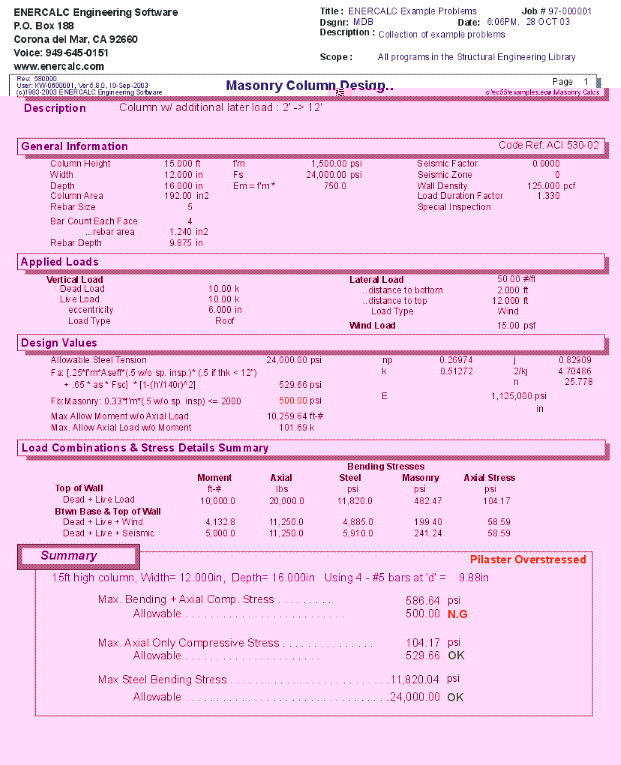
Final Results
At the top of this tab are the final maximum values and their comparable allowables.
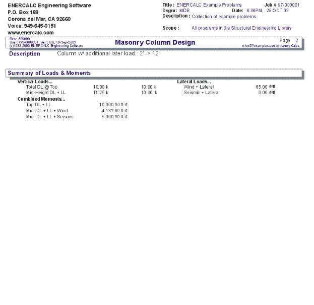
Summary
This area summarizes the calculated vertical loads, lateral loads, and moments that are used for the stress analysis.
Results / Design Values Tab
Top of Column
This area displays the calculated moment, axial load, and stresses at the to of the column. The moments are the result of axial load eccentricity.
Between Base and Top Of Column
This area summarizes the calculated moment, axial loads, and stresses when two different load combinations are used to calculate moments between the top and bottom of the wall (simply span beam moments) due to axial load eccentricity and lateral loads.
Sketch Tab
This tab provides a sketch of the beam with loads and resulting values shown. Using the [Print Sketch] button will print the sketch in large scale on a single sheet of paper.
Printing Tab
This tab allows you to control which areas of the calculation to print. Checking a box will signal that the information described by the item will be printed. However, if there is no information in for a particular selection it will not be printed. So these checkboxes are best described as "If this particular area of the calculations contains data then print it".
Sample Printout